See-through display and head-up display

a display and head-up technology, applied in the field of see-through display, can solve the problems of irregular luminance distribution and color distribution in the image, hmd may consume little power to provide a user with large images,

Active Publication Date: 2012-04-26
PANASONIC CORP
View PDF10 Cites 44 Cited by
  • Summary
  • Abstract
  • Description
  • Claims
  • Application Information

AI Technical Summary

Benefits of technology

[0013]An object of the present invention is to provide a see-through display configured to display quality images.

Problems solved by technology

The HMD may consume little power to provide a user with large images.
For example, if there is a thermal change in wavelength from the light source, diffraction efficiency may go down to cause irregular luminance distribution and color distribution in the image.

Method used


Image

  • See-through display and head-up display
  • See-through display and head-up display
  • See-through display and head-up display

Examples


first embodiment

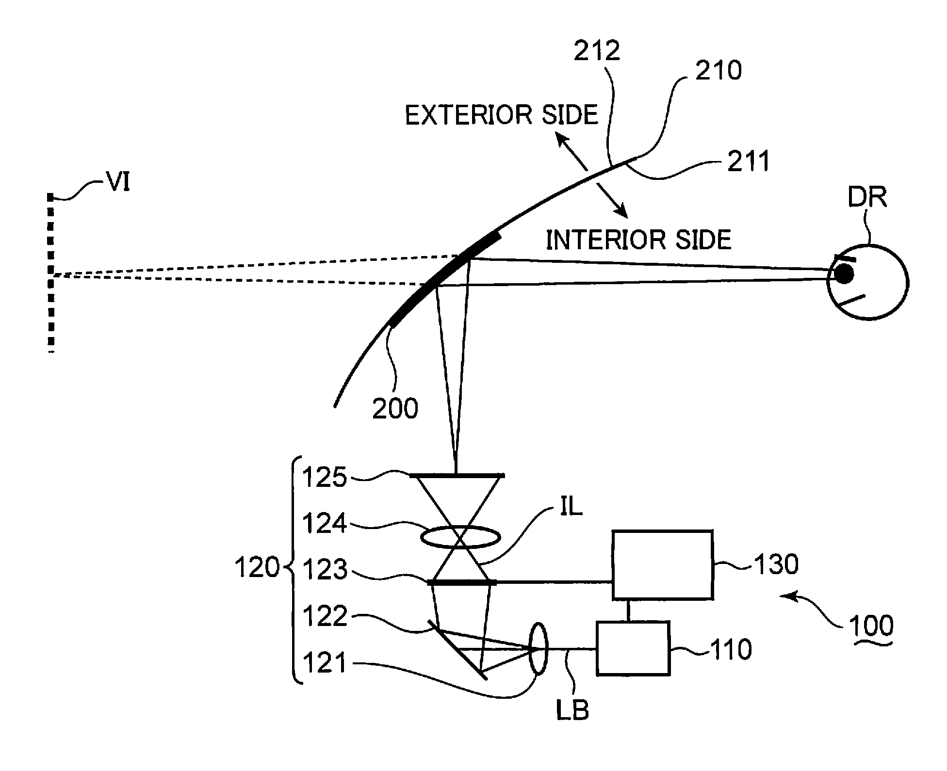
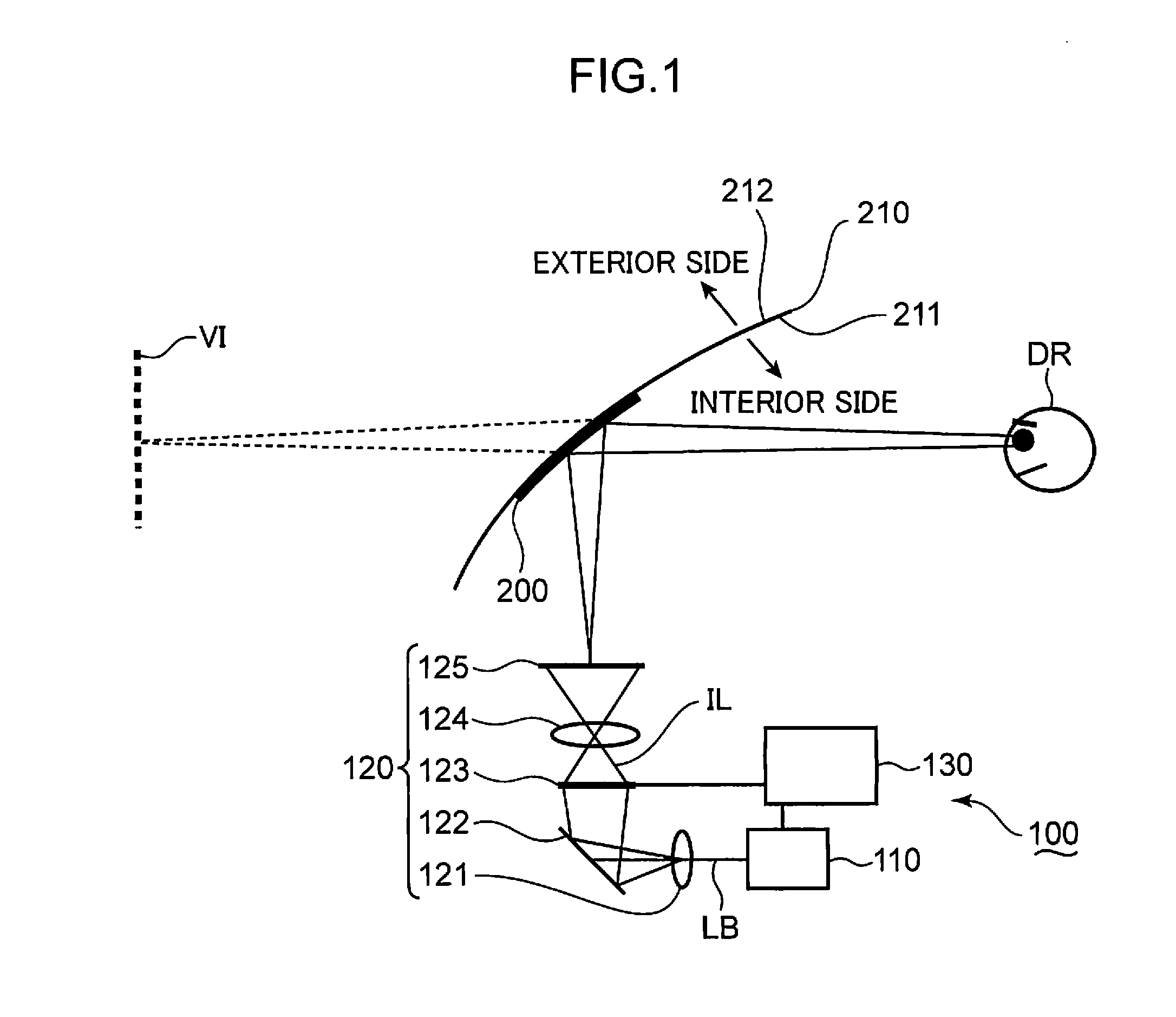
[0051]FIG. 1 is a schematic view of a head-up display (hereafter abbreviated as “HUD”) exemplified as a see-through display according to the first embodiment. The head-up display is described with reference to FIG. 1.

(Configuration of Head-Up Display)

[0052]The HUD 100 schematically shown in FIG. 1 is mounted, for example, on an automobile. An automobile windshield 210 is shown in FIG. 1. The windshield 210 has an inner surface 211 defining an inner boundary of the automobile cabin and an outer surface 212 opposite to the inner surface 211.

[0053]The HUD 100 has a laser source 110 which emits a laser beam LB, a projection optical system 120 which projects the laser beam LB emitted by the laser source 110, and a volume hologram 200 which is attached on the inner surface 211 of the windshield 210. The projection optical system 120 has a lens 121, a return mirror 122, a liquid crystal panel 123, a projection lens 124, and a screen 125. In this embodiment, the laser source 110 is exemplif...

second embodiment

[0166]FIG. 13 is a schematic view of an HUD exemplified as a see-through display according to the second embodiment. The HUD is described with reference to FIGS. 4 and 13.

[0167]The HUD 300 according to the second embodiment has the controller 130A, the dichroic mirrors 151,152, and the projection optical system 120, like the HUD 100A described with reference to FIG. 4. The HUD 300 also comprises a light source 350 including a red wavelength conversion laser source 310R, a green wavelength conversion laser source 310G and a blue wavelength conversion laser source 310B, and a volume hologram 320 attached to the inner surface 211 of the windshield 210. The red, green and blue wavelength conversion laser sources 310R, 310G, 310B are electrically connected to the controller 130A and operated under the control of the controller 130A.

[0168]The red wavelength conversion laser source 310R converts fundamental waves into higher harmonic waves by means of a wavelength conversion element to emi...

third embodiment

[0199]Although the temperature dependency of light wavelength emitted by the light source is taken into consideration in the principles of the first embodiment, the principles of the present embodiment are applicable without any limitation to the temperature dependency of the light emitted by a light source.

[0200]FIG. 16 is a schematic view of an HUD exemplified as a see-through display according to the third embodiment. The HUD is described with reference to FIGS. 4 and 16.

[0201]The HUD 400 according to the third embodiment comprises the dichroic mirrors 151,152, the projection optical system 120 and the volume hologram 200A, like the HUD 100A shown in FIG. 4. The HUD 400 further comprises a light source 450 including a red laser source 410R, a green laser source 410G and a blue laser source 410B, and a controller 430. The controller 430 is electrically connected to the liquid crystal panel 123, the red, green and blue laser sources 410R, 410G, 410B. The liquid crystal panel 123, t...


PUM


Abstract

A see-through display including a light source for emitting light, a projection optical system for projecting the light emitted by the light source, and a volume hologram for deflecting the light projected by the projection optical system. The volume hologram has a linear expansion coefficient of α ( / ° C.) and interference fringes recorded with recording light having a wavelength of Λ (nm). The wavelength of the light emitted by the light source has a temperature dependency of K (nm / ° C.), and the wavelength Λ (nm) and the temperature dependency K (nm / ° C.) satisfy the relationship of 0≦K / Λ≦2α.

Description

TECHNICAL FIELD[0001]The present invention is principally related to a see-through display which is used as an image display apparatus such as head-up displays (HUDs) and head-mount displays (HMDs).BACKGROUND OF THE INVENTION[0002]An image display apparatus called head-up display (HUD) principally displays information which is required for maneuver or operation in automobiles or aircraft cockpits. An automobile driver or aircraft pilot may perceive the information displayed by the HUD as if the displayed information is present in front of the windshield.[0003]An image display apparatus called head-mount display (HMD) is worn in the same manner as ordinary vision correction glasses. A user wearing an HMD may perceive an image displayed by the HMD as if displayed information is present in a space in front of the display lens.[0004]The HUD and the HMD both allow a user to view images through a substantially transparent part such as windshield or lens part, and therefore these image dis...

Claims


Application Information

Patent Timeline
Patent Type & Authority Applications(United States)
IPC IPC(8): G03H1/22G03H1/02
CPCG02B27/01H04N9/3161G02B2027/0112G02B27/0103
Inventor SHIKII, SHINICHISUGIYAMA, KEIJIKADOWAKI, SHINICHI
Owner PANASONIC CORP
Why Eureka
Try Eureka