Periscope device

a periscope and compass technology, applied in the field of periscope devices, can solve the problems of difficult viewing of superposed information by the driver/operator, and achieve the effect of facilitating good image representation and cost-effectiveness

Inactive Publication Date: 2012-04-26
BAE SYSTEMS HAGGLUNDS AKTIEBOLAG
View PDF17 Cites 10 Cited by
  • Summary
  • Abstract
  • Description
  • Claims
  • Application Information

AI Technical Summary

Benefits of technology

[0004]An object of the present invention is to provide a periscope device by means of which visual information may be superposed on the surrounding in the window of the periscope, which is simple, cost efficient and facilitates good representation of the image even in strong light conditions.SUMMARY OF THE INVENTION

Problems solved by technology

A problem is that driver or other operator wishes to be able to see e.g. vehicle information and then needs to turn to a computer screen or the corresponding such that the eye needs to be turned away from the surrounding seen through the periscope.
A problem with such solutions is that the strength of light provided is insufficient which results in difficulties for driver / operator to see the superposed information.

Method used


Image

  • Periscope device
  • Periscope device
  • Periscope device

Examples


first embodiment

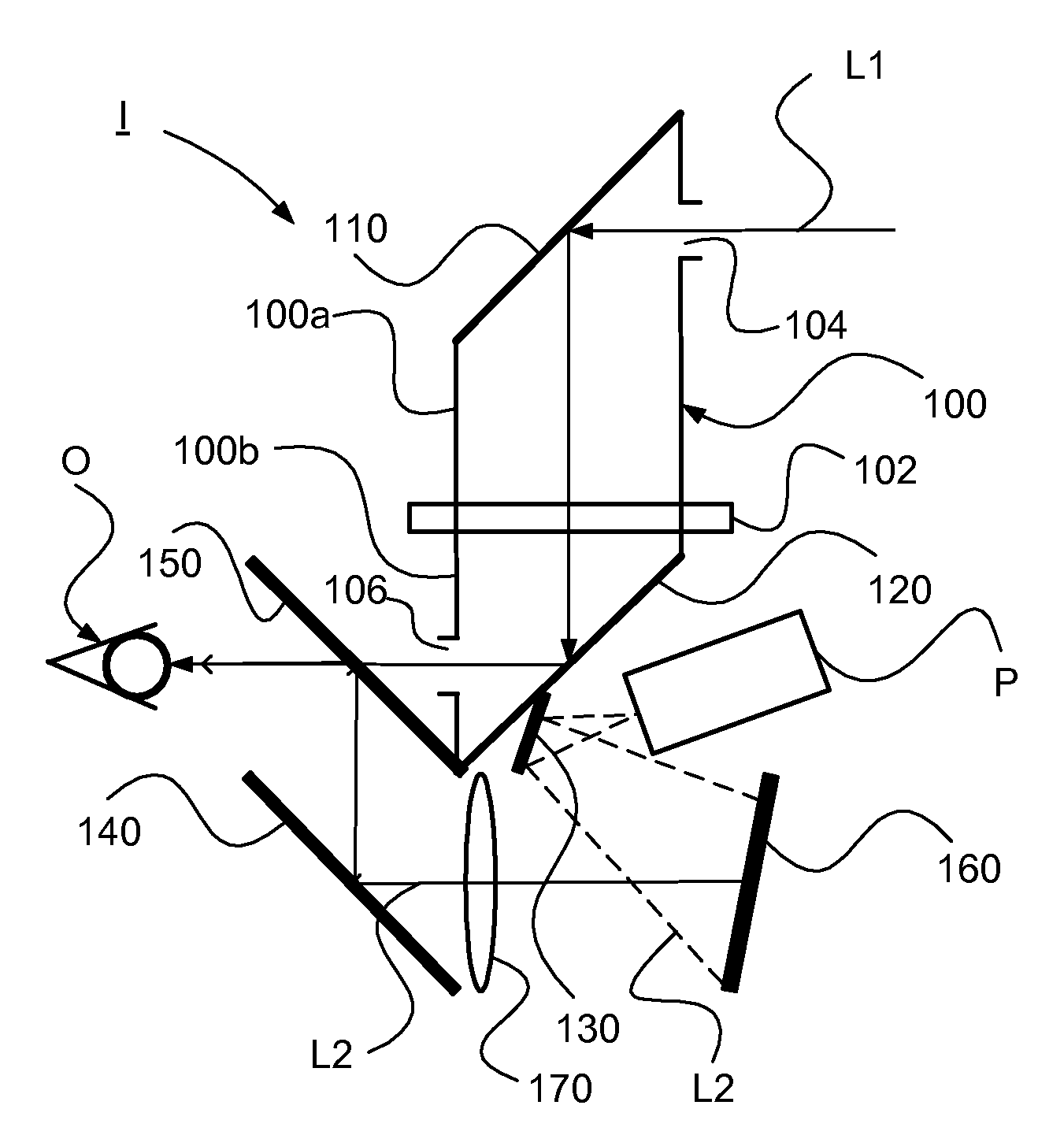
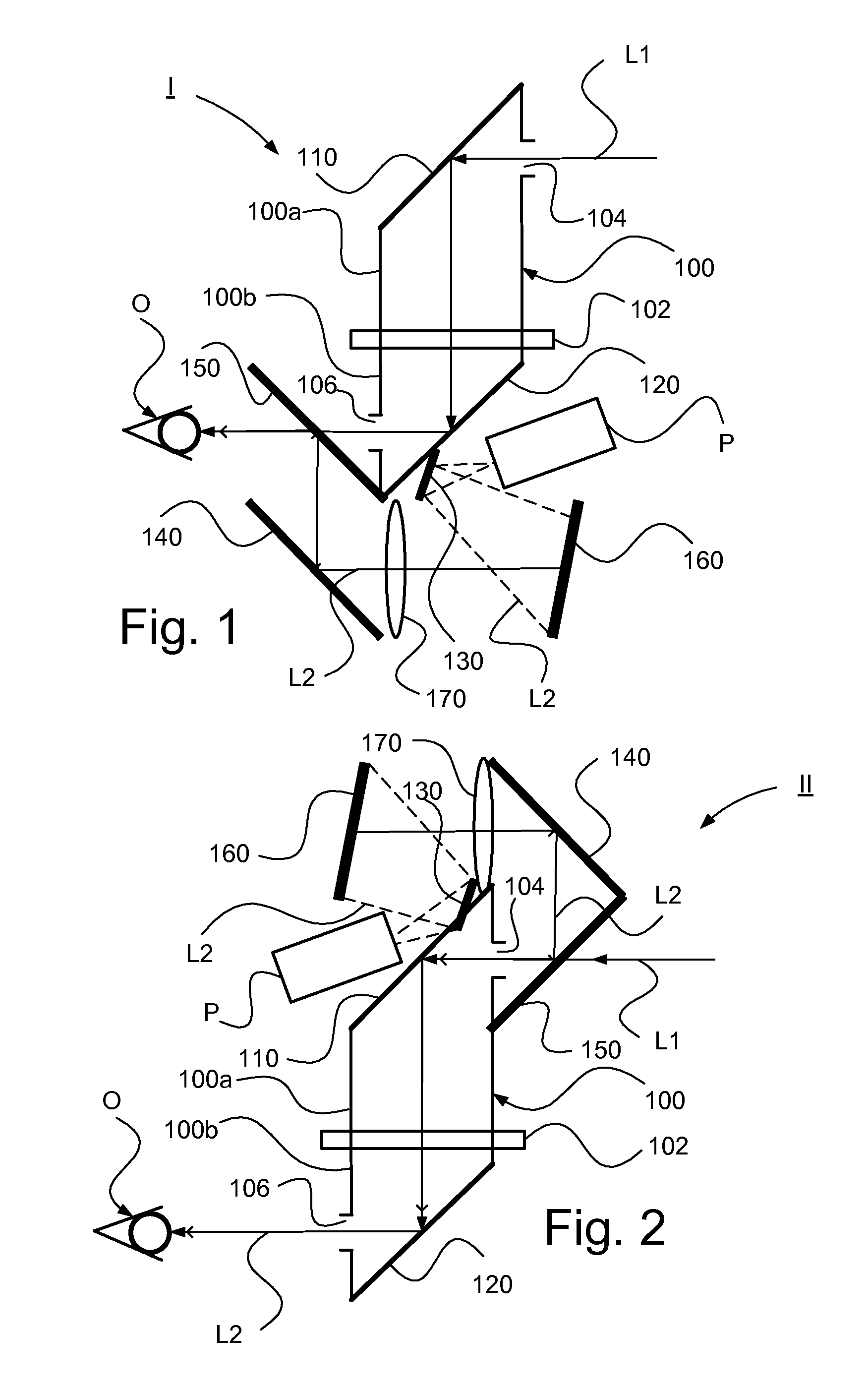
[0040]FIG. 1 schematically illustrates a side view of a periscope device I according to the present invention.

[0041]The periscope device I according to the first embodiment comprises a periscope body 100 and first and second redirecting surfaces 110, 120 according to above, the first and second redirecting surface 110, 120 constituting the surface of a mirroring element such as the surface of a mirror element or a prism element, i.e. reflection surfaces.

[0042]According to the first embodiment the projector P is arranged in connection to the lower portion 100b of the periscope body 100. The projector P is consequently according to this embodiment intended to be arranged in the inner area when the periscope device I is arranged on a vessel such as a vehicle.

[0043]The periscope device I comprises a third redirecting surface 130, which according to this embodiment is constituted by the surface of mirroring elements such as the surface of a mirror element or the surface of a prism elemen...

second embodiment

[0050]FIG. 2 schematically illustrates a side view of a periscope device II according to the present invention.

[0051]The periscope device II according to the second embodiment comprises a periscope body and first and second redirection surfaces 110, 120 according to above, the first and second redirecting surface 110, 120 constituting the surface of a mirroring element such as the surface of a mirror element or a prism element.

[0052]According to a second embodiment the projector P is arranged in connection to the upper portion 10a of the periscope body 100. The projector P is consequently according to this embodiment intended to be arranged in the upper area when the periscope device II is arranged on a vessel such as a vehicle.

[0053]The periscope device II comprises a third redirecting surface, which according to an embodiment is constituted by the surface of mirroring elements such as the surface of a mirror element or the surface of a prism element. The periscope device II furthe...

third embodiment

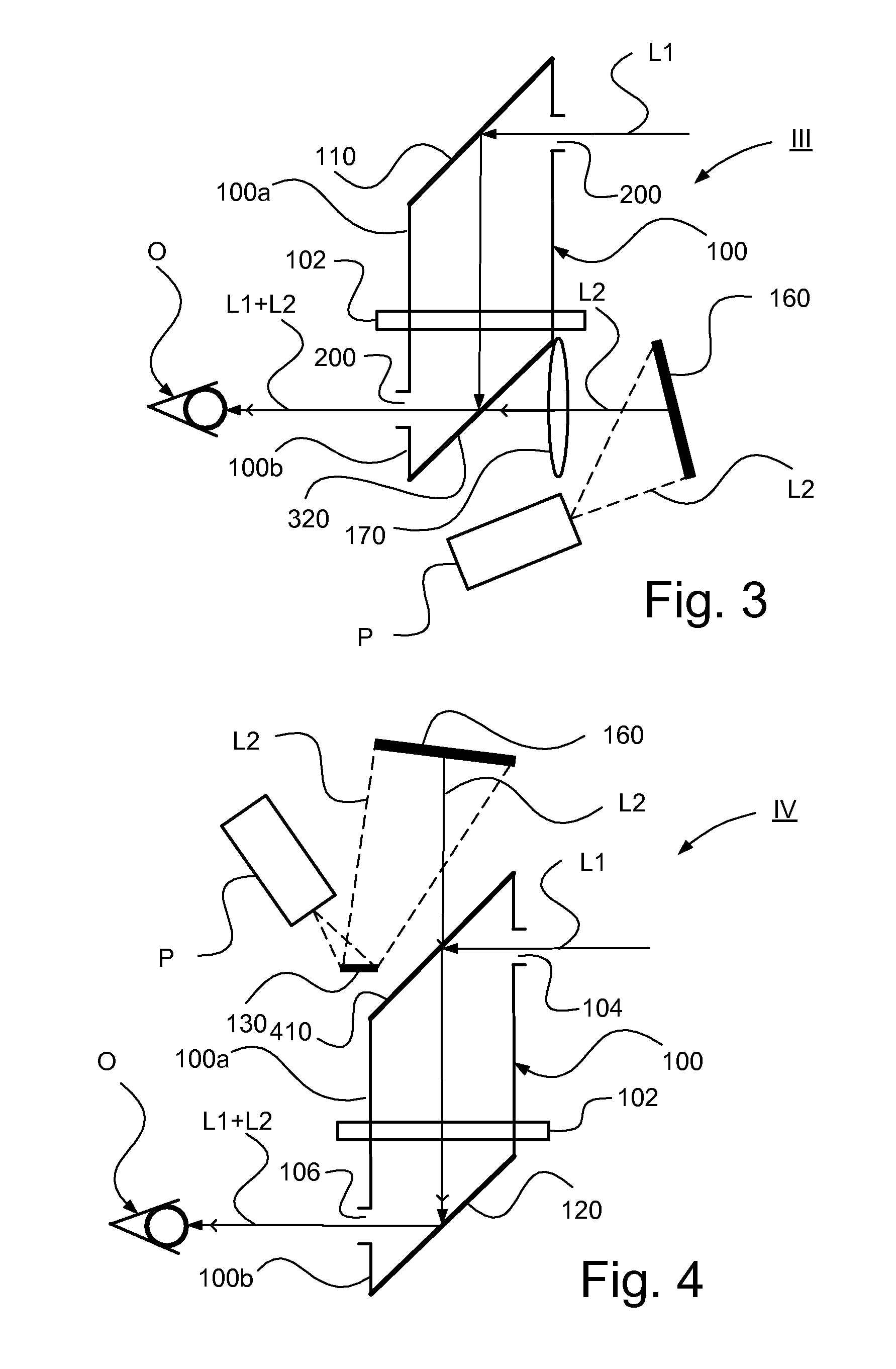
[0061] the projector P is arranged in connection to the lower portion 100b of the periscope body 100. The projector P is according to this embodiment consequently intended to be arranged in the inner area when the periscope device III is arranged on a vessel such as a vehicle.

[0062]The periscope device III comprises a projection surface 160 arranged to receive the light borne information L2 projected from the projector P, wherein the projector P is arranged such that the second light borne information L2 representing visual supplementary information is directed towards the projection surface 160. The projector P is consequently arranged to project the visual supplementary information towards the projection surface 160, wherein the visual supplementary information is created in the shape of an image on the projection surface 160.

[0063]The second redirecting surface 320 is according to this embodiment constituted by a beam splitter 320. The projection surface 160 is arranged to redire...


PUM


Abstract

The invention relates to a periscope device for transmission of a surrounding represented by first light borne information (L1) to the view opening (106), wherein the first light borne information (L1) at the view opening is arranged to be presented together with visual supplementary information represented by second light borne information (L2), wherein the visual supplementary information (L2) is arranged to be provided by means of a projector (P). The invention also relates to a vessel.

Description

TECHNICAL FIELD[0001]The present invention relates to a periscope device according to the preamble in claim 1. The present invention also relates to a vessel.BACKGROUND[0002]In order for drivers or other operators on e.g. military vehicles not having to expose themselves for possible threats but at the same time be able to see the surrounding they are equipped with periscopes. A problem is that driver or other operator wishes to be able to see e.g. vehicle information and then needs to turn to a computer screen or the corresponding such that the eye needs to be turned away from the surrounding seen through the periscope. A solution to this problem is to superpose information from a display element in the optical direct view such that the driver or other operator sees a combined image of the surrounding and desired information from the display in the window of the periscope. LED, OLED and LCD are examples on displays used.[0003]A problem with such solutions is that the strength of li...

Claims


Application Information

Patent Timeline
Patent Type & Authority Applications(United States)
IPC IPC(8): G02B23/08
CPCG02B5/02G02B27/0101G02B23/10G02B23/08
Inventor MANNELQVIST, ANDERSNORDIN, DANIELGUSTAFSSON, TORBJOMCARLEBURG, PER
Owner BAE SYSTEMS HAGGLUNDS AKTIEBOLAG
Why Eureka
Try Eureka