Eureka AIR delivers breakthrough ideas for toughest innovation challenges, trusted by R&D personnel around the world.

Multi-shank nail

a multi-shank, nail technology, applied in the direction of nails, fastening means, screws, etc., can solve the problems of not providing sufficient separation strength for both shanks, high price of typical expansion screws, and inability to meet the needs of fragile materials or foam materials, etc., to achieve enhanced separation effect, easy bending, and improved securing

Active Publication Date: 2012-04-26
YEUN CHANG HARDWARE TOOL
View PDF0 Cites 6 Cited by
  • Summary
  • Abstract
  • Description
  • Claims
  • Application Information

AI Technical Summary

Benefits of technology

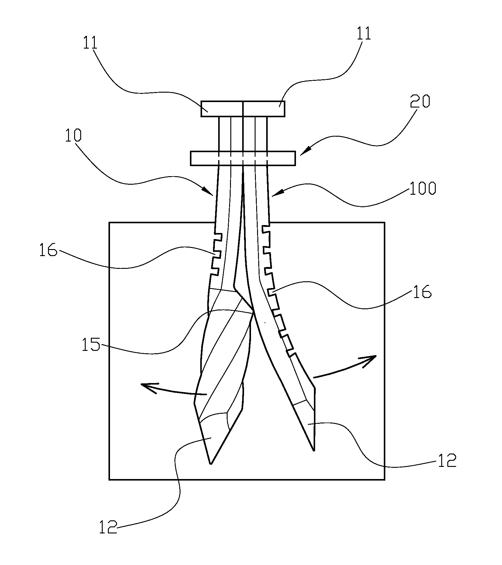
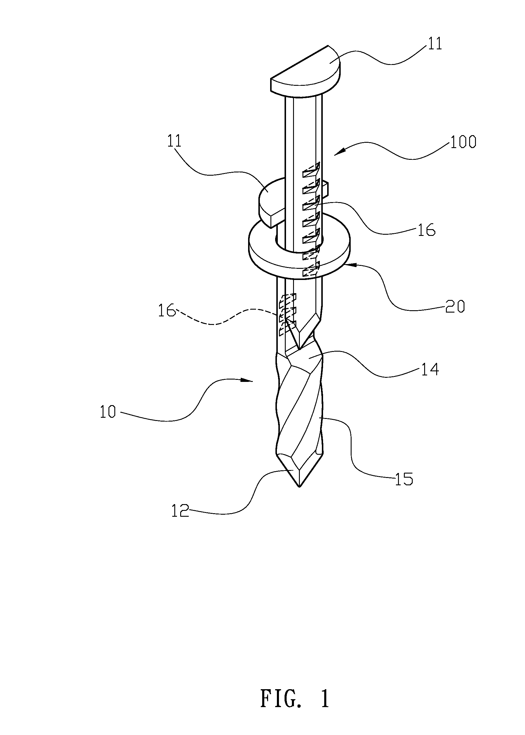
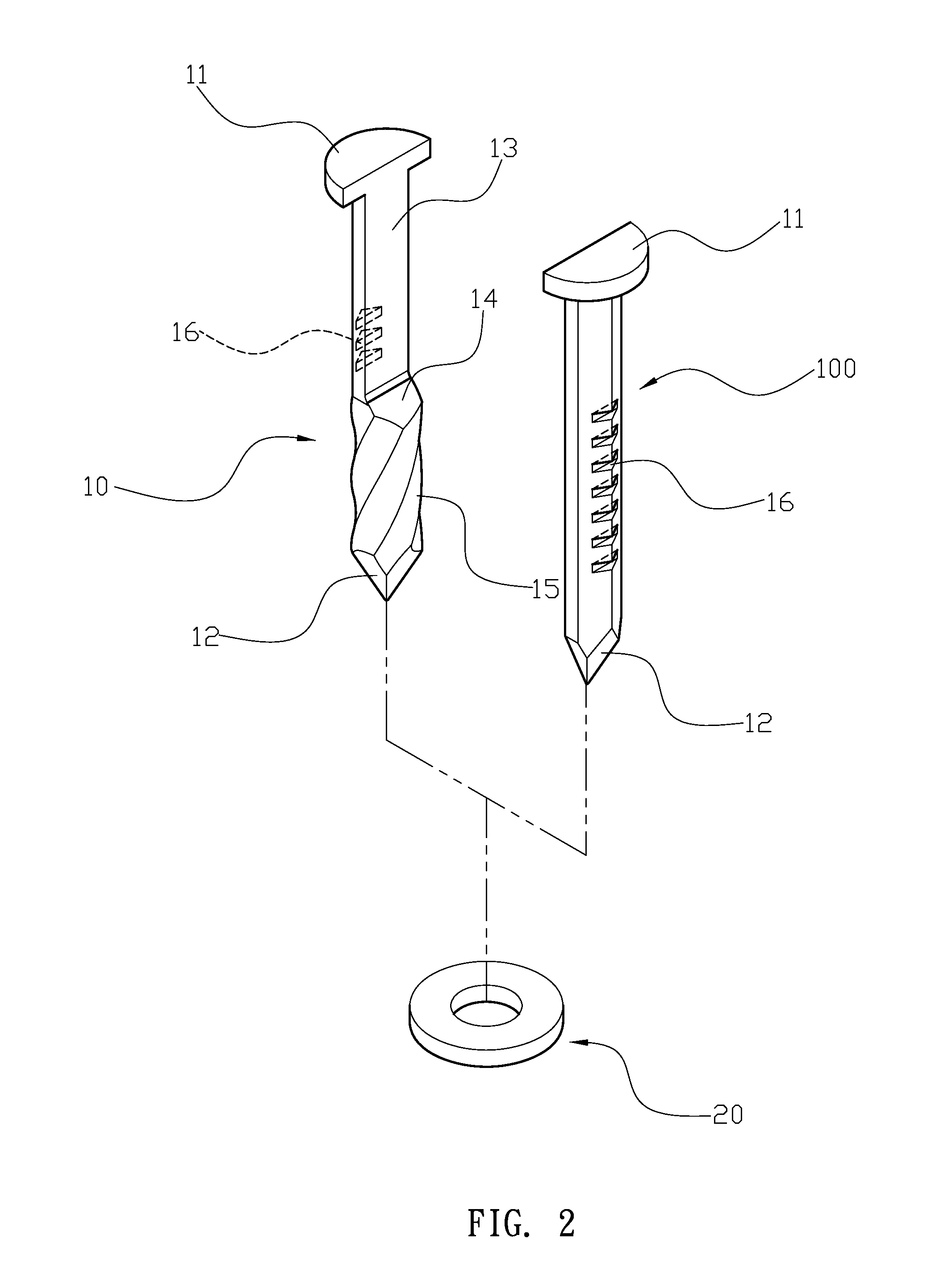
[0009]In order to achieve the above-mentioned objective, a multi-shank nail has a first shank, a second shank and a washer; wherein both of the first shank and the second shank have an enlarged head at their top ends and a point at their lower ends. The first shank has a flat contact surface along its longitudinal length at an upper portion, and the second shank has a shape of a longitudinally cut nail such that the second shank is capable of corresponding to the contact surface on the first shank. The first shank has an inclined face and an extended portion in sequence below the contact surface, and the extended portion has at least one spiraled slot. At least one of the first shank or second shank comprises a plurality of notches opposite the contact surface, and the notches make the first shank or second shank easier to bend.
[0010]With the above-mentioned structure, embodiments of the present invention can provide the following benefits: the first shank and the second shank are able to bend away from each other to provide an improved securing effect, and the inclined face provides a gradual pushing angle to enhance the separation effect.

Problems solved by technology

But the typical expansion screw is expensive due to its complex structure and manufacturing process.
Further, expansion screws are not suitable for fragile materials or foam materials.
However, the above-mentioned structure has the following drawback: the single protruding point 33 does not provide sufficient separation strength for both shanks 30, 300.

Method used


Image

  • Multi-shank nail
  • Multi-shank nail
  • Multi-shank nail

Examples


Embodiment Construction

[0018]First, please refer to FIG. 1 and FIG. 2. A nail comprises a first shank 10, a second shank 100 and a washer 20. Both of the first shank 10 and the second shank 100 have an enlarged head 11 at their top ends and a tapered point 12 at their lower ends. The first shank 10 has a flat contact surface 13 along its longitudinal length along an upper portion, and the second shank 100 has the shape of a longitudinally cut nail such that the second shank 100 is capable of corresponding to the contact surface 13 on the first shank 10. The first shank 10 has an inclined face 14 and an extended portion 15 in sequence below the contact surface 13. The extended portion 15 has a plurality of spiraled slots. The first shank 10 and second shank 100 also comprise a plurality of parallel notches 16 opposite the contact surface 13, and the notches 16 make the first shank 10 and second shank 100 easier to bend.

[0019]Please refer to FIG. 3 to FIG. 5. The washer is jacketed onto the first and second...


PUM


Abstract

A multi-shank nail has a first shank, a second shank and a washer; wherein both of the first shank and the second shank have an enlarged head at their top ends and a point at their lower ends. The first shank has a flat contact surface along its longitudinal length at an upper portion, and the second shank has a shape of a longitudinally cut nail such that the second shank is capable of corresponding to the contact surface on the first shank. The first shank has an inclined face and an extended portion in sequence below the contact surface. At least one of the first shank or second shank comprises a plurality of notches opposite the contact surface, and the notches make the first shank or second shank easier to bend.

Description

BACKGROUND OF THE INVENTION[0001]1. Field of the Invention[0002]The present invention relates to a multi-shank nail, and more particularly to a multi-shank nail that provides an improved securing effect.[0003]2. Description of the Related Art[0004]Currently, expansion screws are often used for securing objects to a wall. But the typical expansion screw is expensive due to its complex structure and manufacturing process. Further, expansion screws are not suitable for fragile materials or foam materials.[0005]Therefore, a multi-shank nail was developed. Please refer to FIG. 6. The multi-shank nail comprises two shanks 30, 300 and a washer 40. The two shanks 30, 300 both have a shape of a longitudinally cut nail, with the two shanks 30, 300 forming a complete, whole nail. The two shanks 30, 300 both have an enlarged head 31 at their top ends and a taped point 32 at their lower ends. One flat surface of the shank 300 has a protruding point 33. For actual usage, the washer 40 is jacketed...

Claims


Application Information

Patent Timeline
IPC IPC(8): F16B15/04
CPCF16B15/04F16B13/085
Inventor HUNG, YING-FENG
Owner YEUN CHANG HARDWARE TOOL
Why Eureka
Eureka Blog
Learn More