
Method of surge protection for a dynamic compressor using a surge parameter

a dynamic compressor and surge protection technology, applied in the field of dynamic compressors, can solve the problems of inability to measure the volumetric flow and the polytropic head in practice, the amount of gas that passes through the compressor, and damage to the compressor

Inactive Publication Date: 2012-04-26
ENERGY CONTROL TECH
View PDF8 Cites 2 Cited by
  • Summary
  • Abstract
  • Description
  • Claims
  • Application Information

AI Technical Summary

Benefits of technology

This approach provides enhanced real-time surge protection with high dynamic sensitivity, ensuring effective prevention of compressor damage by accurately accounting for multiple variables and maintaining a safety margin, even under varying conditions.

Problems solved by technology

A problem associated with dynamic compressors is the amount of gas that passes through the compressor.
Specifically, if an insufficient amount of gas flows through the compressor, a surge occurs within the system causing damage to the compressor.
Problems in systems such as that taught by Agar and Staroselsky exist because measuring the volumetric flow and the polytropic head in practice is not practical.
There are problems associated with molecular weight and gas density determinations causing these measurements to be inadequate for real time surge protection.
However, existing methods for invariant parameter calculations do not completely account for variability in gas compressibility or gas specific heat ratio.
As a result, variations in gas composition tend to make the surge parameter and surge limit line move resulting in operating problems.
In addition, existing methods for the distance to surge calculation method is dynamically insensitive or sluggish especially as the compressor load increases.

Method used


Image

  • Method of surge protection for a dynamic compressor using a surge parameter
  • Method of surge protection for a dynamic compressor using a surge parameter
  • Method of surge protection for a dynamic compressor using a surge parameter

Examples


Embodiment Construction

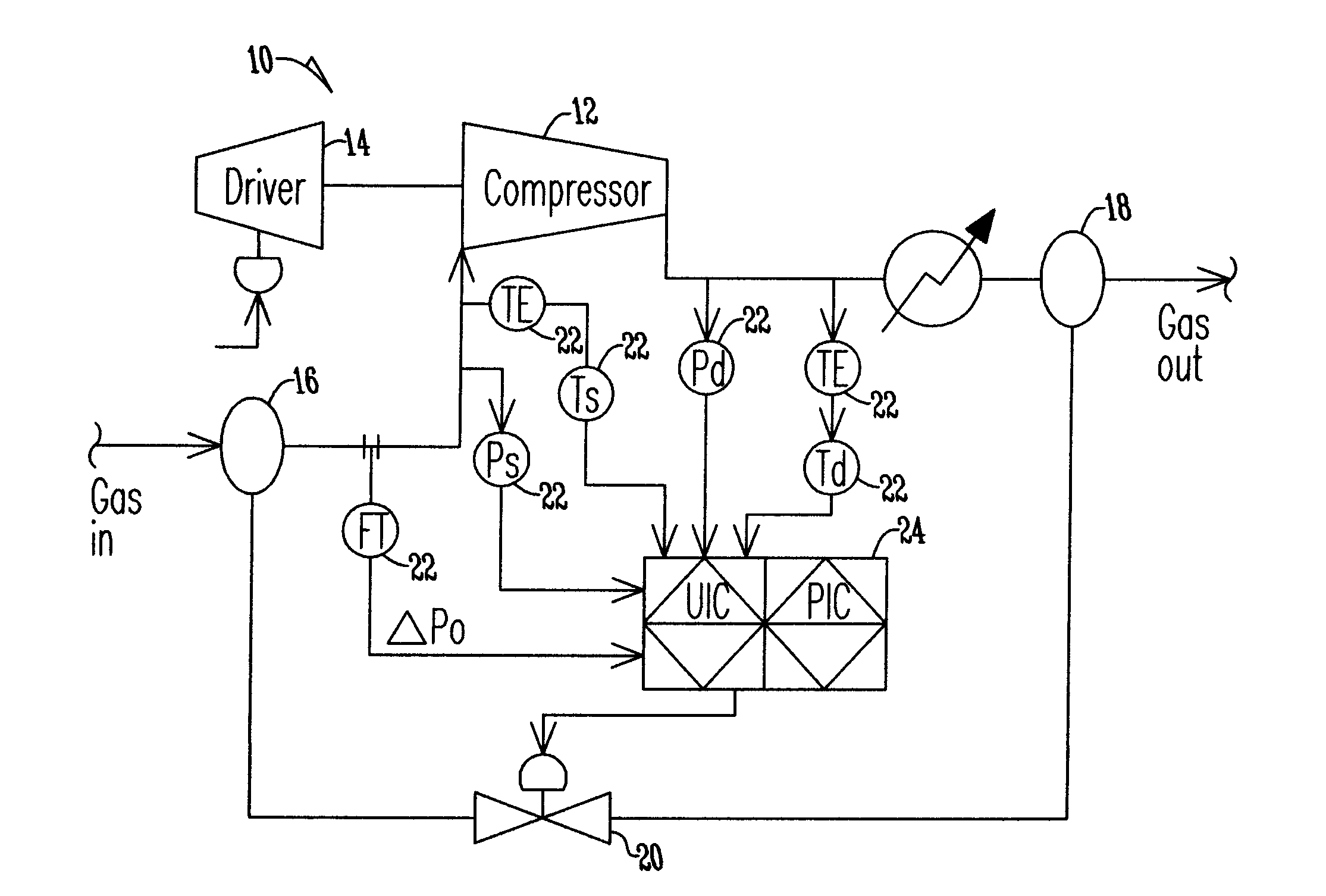
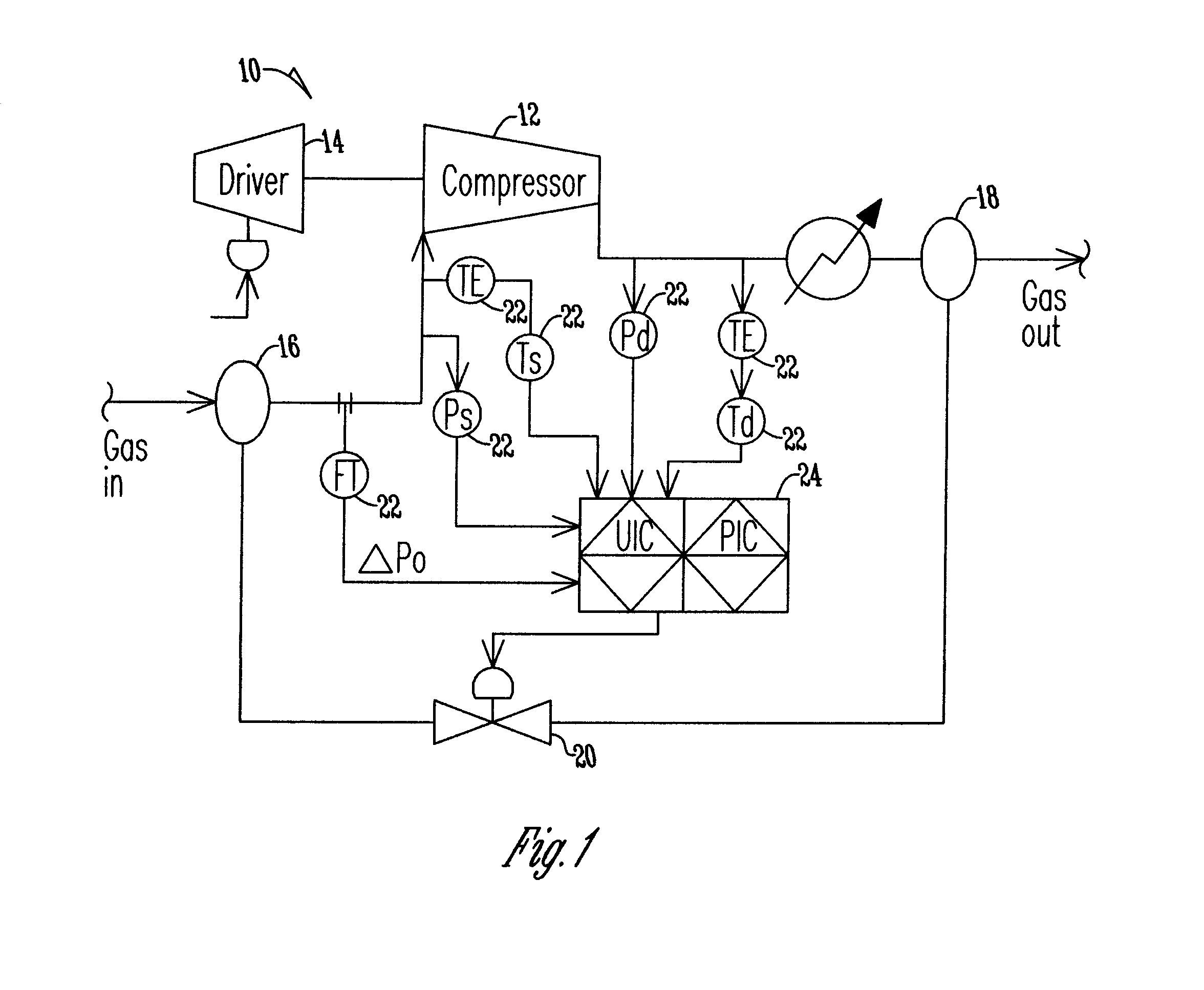
[0015]FIG. 1 shows a dynamic compressor 10 that includes a compressor 12 that is driven by a compressor driver 14. The compressor driver is of any type including a motor, gas turbine, steam turbine, expander or the like. The compressor 12 has a gas inlet 16 and a gas outlet 18 wherein gas flows through the compressor 12 to be compressed. An anti-surge or recycle valve 20 is fluidly connected between the gas inlet 16 and gas outlet 18 so that when the anti-surge valve 20 opens a fluid flow path exists to convey gas from the gas outlet 18 to the gas inlet 16. A plurality of sensors 22 including pressure sensors, temperature sensors, flow measurement sensors and the like are placed throughout the dynamic compressor 10 in order to determine processed conditions for the components of the dynamic compressor including the compressor 12, the driver 14, the gas inlet 16, and gas outlet 18 and the anti-surge valve 20. The plurality of sensors 22 are electrically connected to the control syste...


PUM


Abstract

A method of surge protection for a dynamic compressor that has a corresponding compressor map. A control system continually calculates an equivalent polytropic head parameter in order to define a surge limit line. The system then calculates a control parameter and determines the distance the control parameter to the surge limit line wherein the control parameter is dynamic to changes in compressor load and invariant to changes in suction conditions and gas compressibility. As a result of the distance of the control parameter to the surge limit line, the surge valve of a dynamic compressor is actuated to prevent surge.

Description

BACKGROUND OF THE INVENTION[0001]The present invention is directed toward a dynamic compressor. More specifically, the present invention is directed toward a method of surge protection utilizing an equivalent map surge parameter.[0002]A typical dynamic compressor has a gas inlet and a gas outlet wherein the compressor is driven by a compressor driver so that the gas, while flowing through the compressor, is compressed. A problem associated with dynamic compressors is the amount of gas that passes through the compressor. Specifically, if an insufficient amount of gas flows through the compressor, a surge occurs within the system causing damage to the compressor. Because of the high price of compressors great care must be taken to ensure that compressors are not damaged.[0003]To minimize damage to compressors as a result of lack of gas flow at an inlet an anti-surge or recycling valve is utilized by dynamic compressors to take gas from the outlet of the compressor and recycle it back ...

Claims


Application Information

Patent Timeline
Patent Type & Authority Applications(United States)
IPC IPC(8): F04B49/06
CPCF04D27/0207
Inventor NARAYANAN, KRISHNANREINKE, PAUL
Owner ENERGY CONTROL TECH
Learn More