
Parking apparatus for automatic transmission

a technology of automatic transmission and parking apparatus, which is applied in the direction of gearing details, braking systems, transportation and packaging, etc., can solve the problems of large amount of working time, difficulty in forming housing protrusion, and inconvenient work, so as to improve work and productivity, reduce cost, and remove work and time

Inactive Publication Date: 2012-05-03
HYUNDAI MOTOR CO LTD +1
View PDF4 Cites 7 Cited by
  • Summary
  • Abstract
  • Description
  • Claims
  • Application Information

AI Technical Summary

Benefits of technology

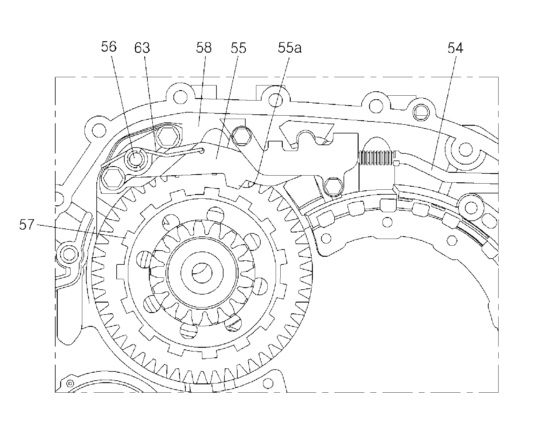
[0015]Various aspects of the present invention are directed to provide a parking apparatus for an automatic transmission that makes it possible to remove work and time for forming a housing protrusion by fixing a sprag shaft inserted in a shaft groove of a transmission housing, not using the housing protrusion, but using a specific assembly device, and accordingly, can improve convenience of work and productivity and reduce the cost because it can be generally used for all other types of transmissions.
[0018]The parking apparatus may further include a stopper plate that may be fitted on the first portion of the sprag shaft in close contact to a front surface of the sprag bracket, may be fixed to the sprag bracket when the sprag bracket may be fixed to the transmission housing, so as to prevent the sprag shaft from being decoupled from the transmission housing by coming in contact with the locking step when the sprag shaft moved to come out from the shaft groove.
[0019]The parking apparatus may further include a fixing clip that may be fixed on the second portion of the sprag shaft with a predetermined distance from the stopper plate along the longitudinal axis of the sprag shaft so as to prevent the sprag return spring from being decoupled from the sprag shaft.
[0022]According to the exemplary embodiments of the present invention, it is possible to easily mount a sprag shaft by holding the sprag shaft with a sprag bracket and a stopper plate, improve productivity by decreasing the work time, reduce the cost by being commonly used for all other types of transmissions, and remove the problems due to interference with other parts, thereby achieving free design.

Problems solved by technology

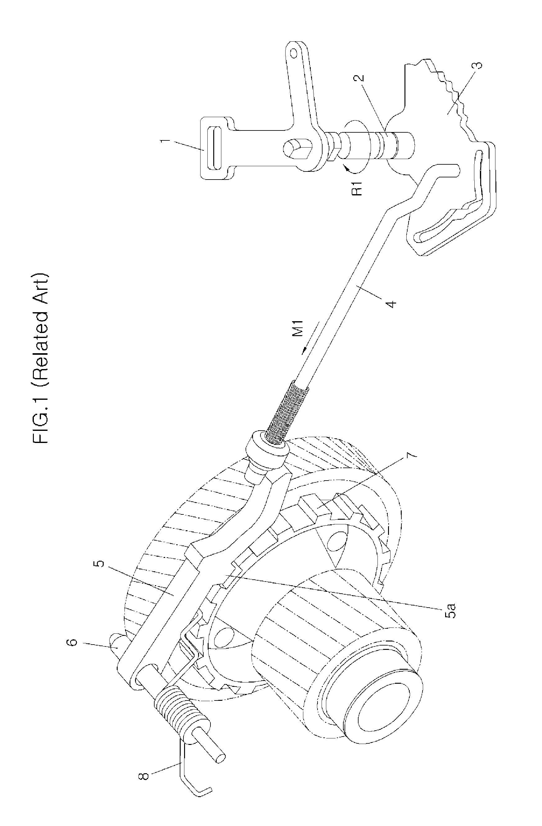
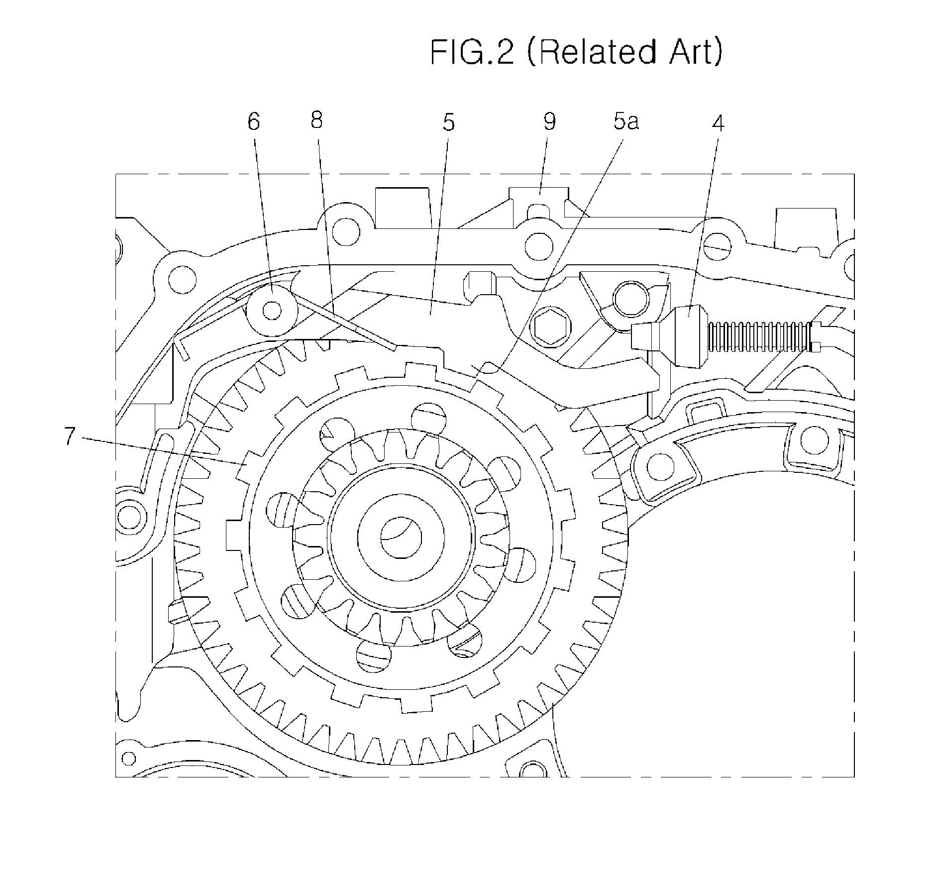
However, in the structure of the related art in which sprag shaft 6 is mounted held by housing protrusion 11a of converter housing 11, it is very inconvenient and difficult to form housing protrusion 11a on converter housing 11 and adjust the length of housing protrusion 11a to fit to the length of sprag shaft 6, such that convenience of work decreases and a large amount of working time is needed, and thus, productivity decreases.

Method used


Image

  • Parking apparatus for automatic transmission
  • Parking apparatus for automatic transmission
  • Parking apparatus for automatic transmission

Examples


Embodiment Construction

[0033]Reference will now be made in detail to various embodiments of the present invention(s), examples of which are illustrated in the accompanying drawings and described below. While the invention(s) will be described in conjunction with exemplary embodiments, it will be understood that the present description is not intended to limit the invention(s) to those exemplary embodiments. On the contrary, the invention(s) is / are intended to cover not only the exemplary embodiments, but also various alternatives, modifications, equivalents and other embodiments, which may be included within the spirit and scope of the invention as defined by the appended claims.

[0034]Hereinafter, exemplary embodiments of the present invention will be described in detail with reference to the accompanying drawings.

[0035]In a parking apparatus for an automatic transmission according to the exemplary embodiments of the present invention, as shown in FIGS. 4 to 7, a control lever 51 that rotates with operati...


PUM


Abstract

A parking apparatus for an automatic transmission, may include a sprag shaft having a first portion and a second portion extending from the first portion, wherein an end of the first portion may be inserted in a shaft groove formed in a transmission housing, and a sprag having one end fitted around the first portion of the sprag shaft to rotate about the sprag shaft, a sprag bracket fitted around the first portion of the sprag shall to cover the end of the sprag therein, wherein the second portion protrudes through the sprag bracket and the sprag bracket may be fixed to the transmission housing, and a sprag return spring mounted on the second portion protruding through the sprag bracket, wherein an end of the sprag return spring may be supported by the transmission housing and the other end thereof may be supported by the sprag.

Description

CROSS-REFERENCE TO RELATED APPLICATIONS[0001]The present application claims priority to Korean Patent Application Number 10-2010-0108589 filed Nov. 3, 2010, the entire contents of which application is incorporated herein for all purposes by this reference.BACKGROUND OF THE INVENTION[0002]1. Field of the Invention[0003]The present invention relates to a parking apparatus for an automatic transmission, and more particularly, to a parking apparatus for an automatic transmission for the installation structure of a sprag shaft and a sprag return spring.[0004]2. Description of Related Art[0005]In general, automatic transmissions are equipped with a parking apparatus that keeps a vehicle stopped by locking a parking gear on an output shaft in a P-range (parking range) with a sprag.[0006]In the parking apparatus, a parking rod operates the sprag when a select lever is moved to the P-range, and the sprag is inserted in a concave-convexo portion on the outer circumferential of the parking gea...

Claims


Application Information

Patent Timeline
Patent Type & Authority Applications(United States)
IPC IPC(8): B60T1/00
CPCF16H63/3416Y10T74/19637Y10T74/2137
Inventor KIM, WOOYEOL
Owner HYUNDAI MOTOR CO LTD
Learn More