Electric sail with voltage multipliers in tethers

Active Publication Date: 2012-05-03
POSTQ IPR OY
View PDF4 Cites 8 Cited by
  • Summary
  • Abstract
  • Description
  • Claims
  • Application Information

AI Technical Summary

Benefits of technology

[0009]The idea is to move high voltage generation for the tethers out to the tethers, possibly tens of meters or more out from the body of the spacecraft, such that risk of sparks, arcs, or

Problems solved by technology

However, increasing the voltage of the tethers is difficult, because near the hub the tethers are relatively close to each other,

Method used


Image

  • Electric sail with voltage multipliers in tethers
  • Electric sail with voltage multipliers in tethers
  • Electric sail with voltage multipliers in tethers

Examples


Embodiment Construction

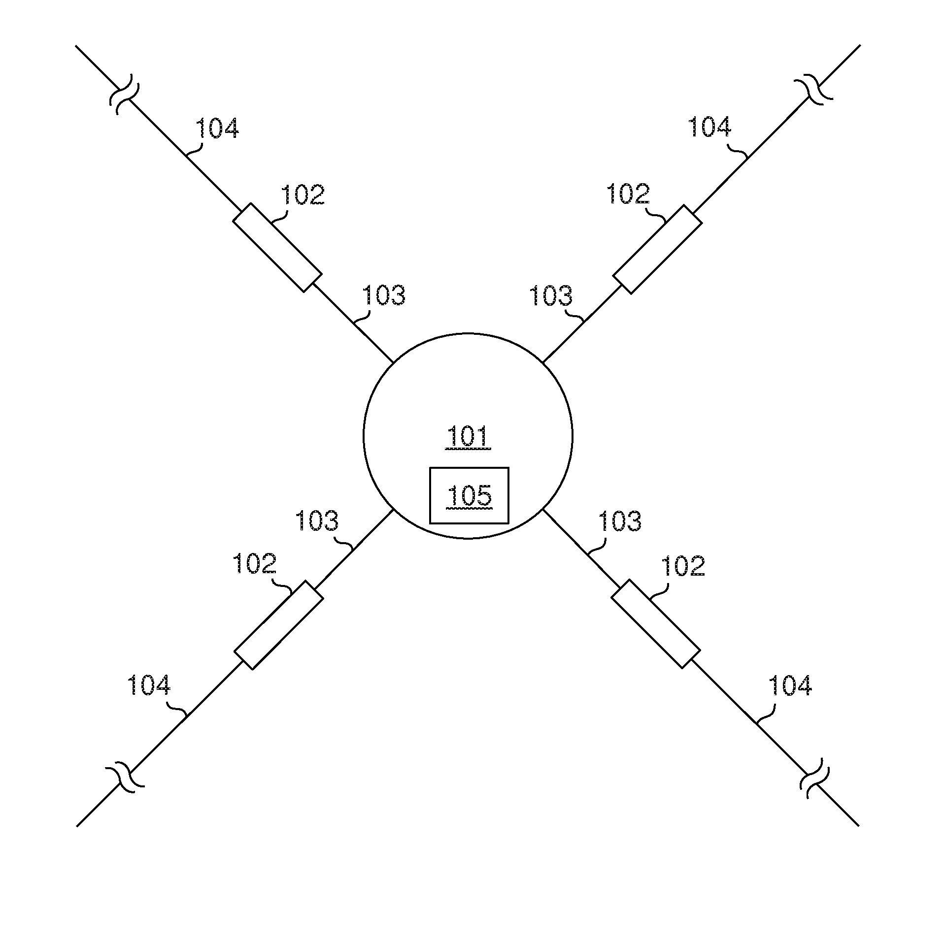
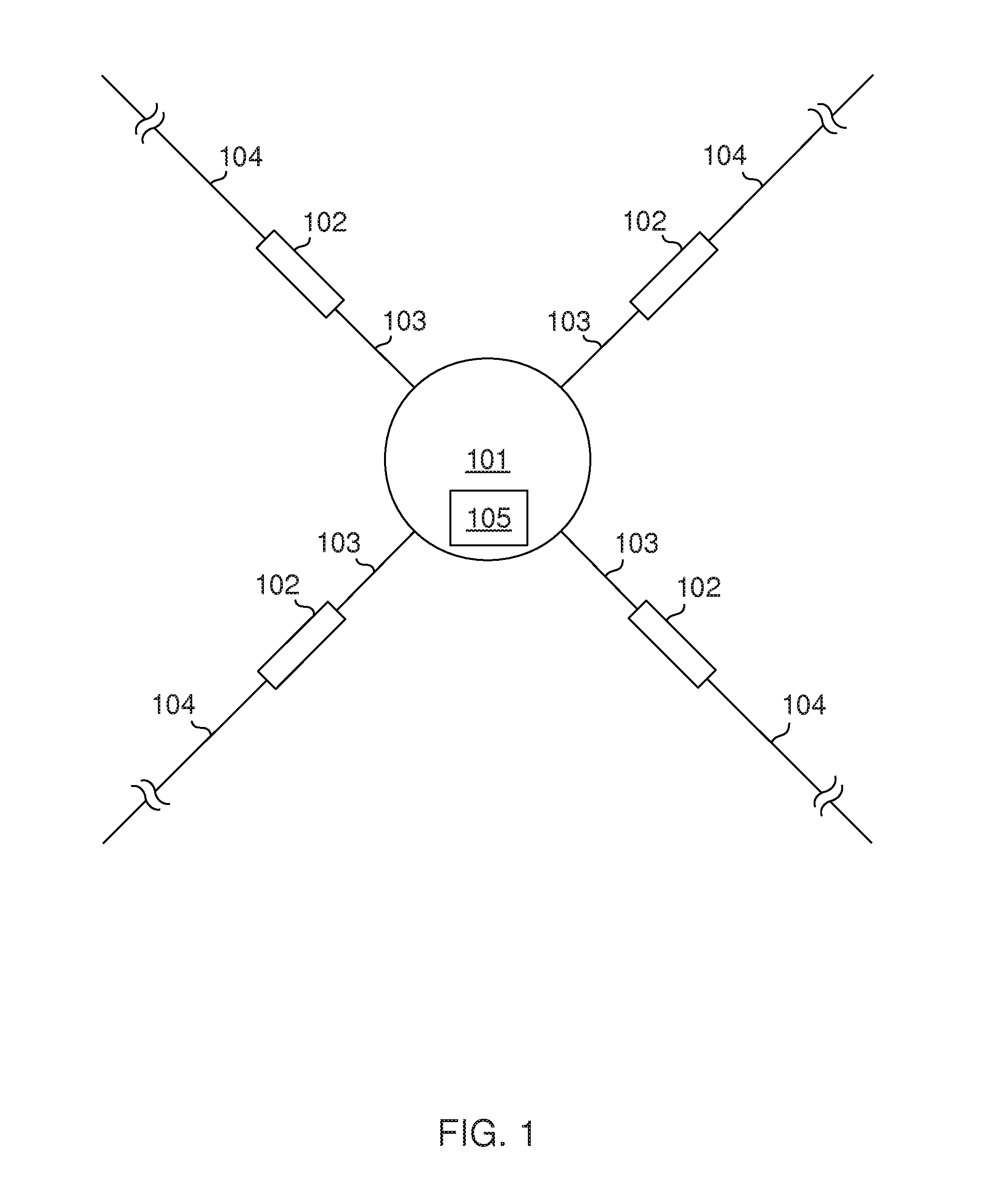
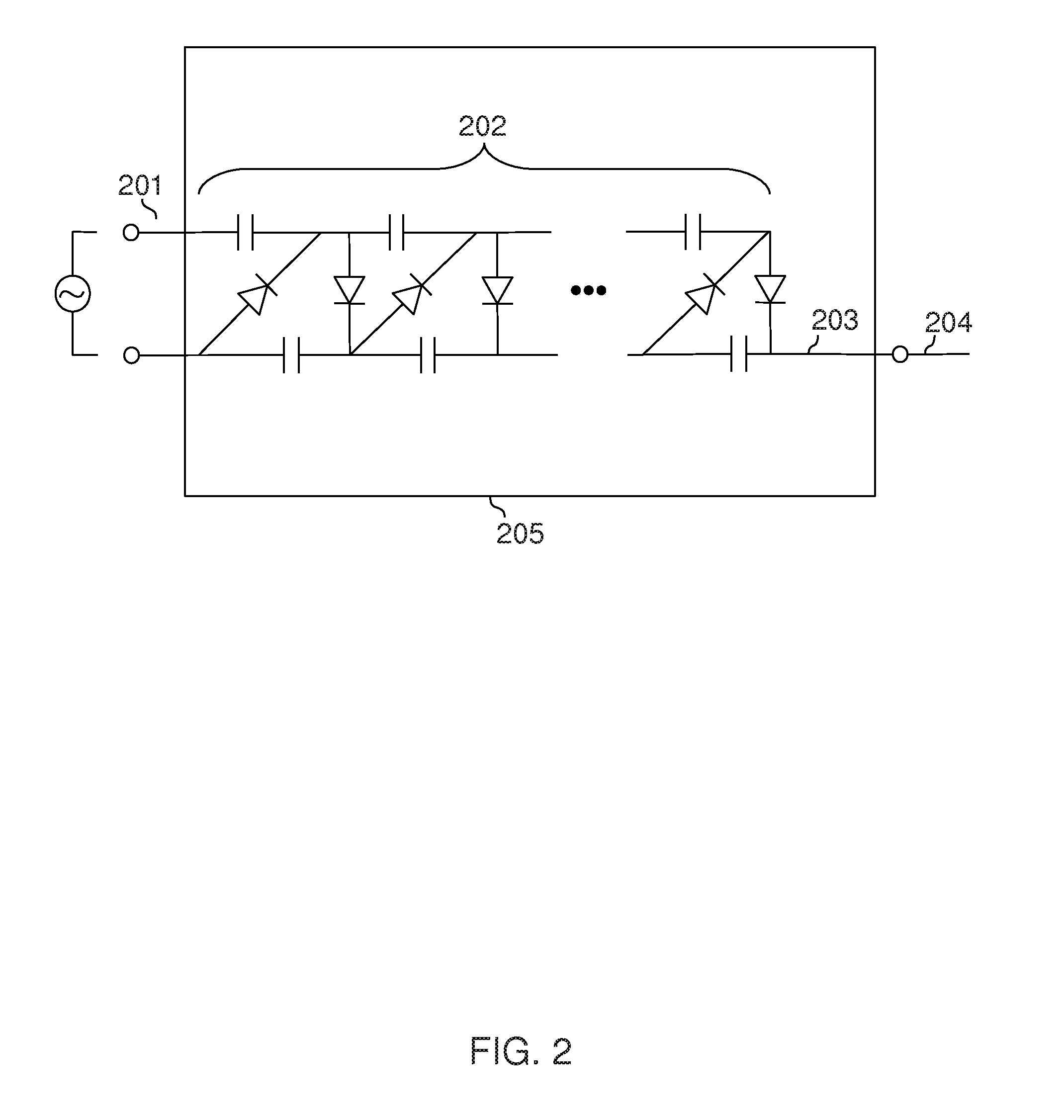
[0026]Voltage multipliers for generating high voltages for tethers of an electric sail are moved out from the body of the spacecraft to locations where relatively high isolation distances are available between conducting components that are at high potential differentials. Such isolation makes possible much higher voltages at the tethers, which means higher charges, which means higher thrust obtained from the same area of the sail. Increasing the thrust reduces travel times, increases practical spacecraft loads, and allows the use of shorter tethers for the same thrust, therefore enabling new applications and bringing cost savings. Increasing the voltage may be a much more cost-efficient and lower-weight way of increasing thrust than increasing area. It is also likely to yield better tolerance against micrometeors than a larger sail with more tether area.

[0027]A further potential advantage of increasing tether voltage may be a reduction in the current flowing in the tether, which ma...


PUM


Abstract

The effective area of an electric sail depends on the voltage applied to tethers. The use of higher voltages is made possible by moving voltage multipliers to tethers, perhaps 100 meters out from the body of the spacecraft.

Description

CROSS-REFERENCE TO RELATED APPLICATIONS[0001]Not ApplicableINCORPORATION-BY-REFERENCE OF MATERIAL SUBMITTED ON ATTACHED MEDIA[0002]Not ApplicableTECHNICAL FIELD[0003]The invention relates to spacecraft propulsion, and particularly to using the solar wind for propulsion using an electric sail.BACKGROUND OF THE INVENTION[0004]Electric sails are a promising propulsion method for relatively low-cost and high-performance spacecraft within the solar system. They are similar to solar sails, but use solar wind as a source of thrust.[0005]In known designs the electric sail consists of tethers arranged radially from a central, rotating hub, or of some kind of network of wires, tethers, or similar narrow structures covering a relatively large area. Solar sail designs frequently use thin foil.[0006]For further information on the state of the art in electric sails, see the US patent application 2007 / 0205331 A1 (P. Janhunen: Electric Sail for Producing Spacecraft Propulsion); P. Janhunen: Electri...

Claims


Application Information

Patent Timeline
IPC IPC(8): B64G1/10B64G1/40
CPCB64G1/407
Inventor YLONEN, TATU J.
Owner POSTQ IPR OY
Why Eureka
Try Eureka