Concrete having excellent explosion resistance

a technology of exploding resistance and concrete, which is applied in the direction of sustainable waste treatment, solid waste management, natural mineral layered products, etc., can solve the problems of a larger separation on this side, etc., and achieve the effect of reducing the damage volume, reducing the risk of injuring persons within the structure, and reducing the volume of concr

Inactive Publication Date: 2009-06-25
TOYOBO CO LTD
View PDF6 Cites 5 Cited by
  • Summary
  • Abstract
  • Description
  • Claims
  • Application Information

AI Technical Summary

Benefits of technology

[0010]The present invention has been made in view of the above state, and it is an object of the present invention to provide a concrete which can suppress extensive destruction of a structure by explosion by the use of explosives and prevent injuries of persons within the structure through suppressing the flying of concrete broken pieces by a blasting impact.
[0011]Further, it is also an object of the present invention to provide a structure in which the weight of the structure can be reduced by the use of a thin concrete plate having excellent exploding resistance and adequate exploding resistance can be realized by stacking the thin concrete plates.
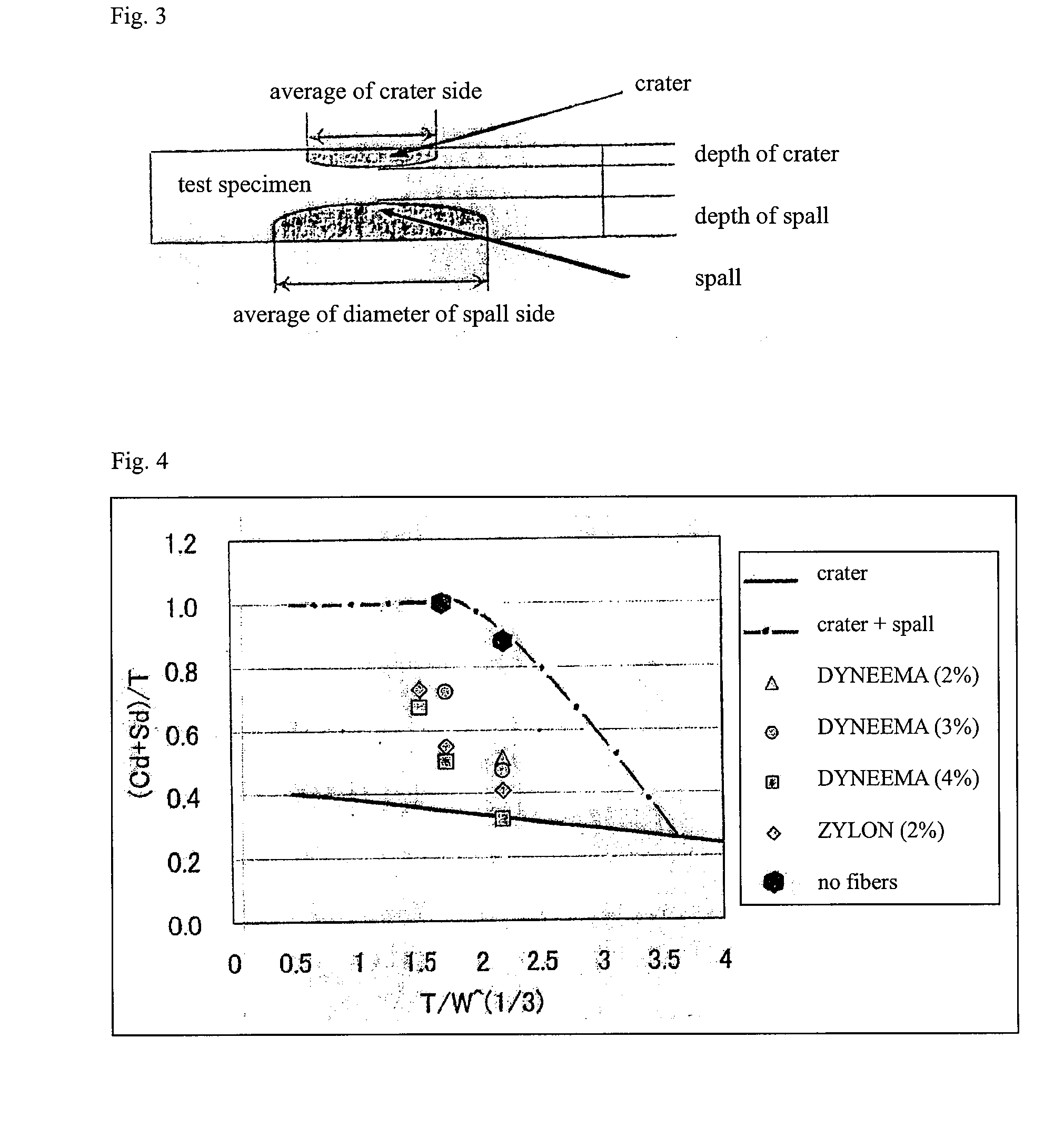
[0013]In the present invention, a concrete obtained by mixing high-strength fibers has the effect of reducing the destroyed volume of the concrete in the explosion by the use of explosives. More specifically, upon explosion of an explosive material near a structure, a part of the structure is separated by explosion energy. In general, the separation of the structure on the side opposite to the side facing explosion is larger than that on the side facing the explosion, and the separation on this side has a larger risk of injuring persons within the structure. Since the present invention has the effect of reducing the separated volume in the acts of blasting a concrete structure using explosives such as terrorism, it can be used as a member for lifesaving or for preventing the collapse of the structure.

Problems solved by technology

In general, the separation of the structure on the side opposite to the side facing explosion is larger than that on the side facing the explosion, and the separation on this side has a larger risk of injuring persons within the structure.

Method used


Image

  • Concrete having excellent explosion resistance
  • Concrete having excellent explosion resistance

Examples


example 1

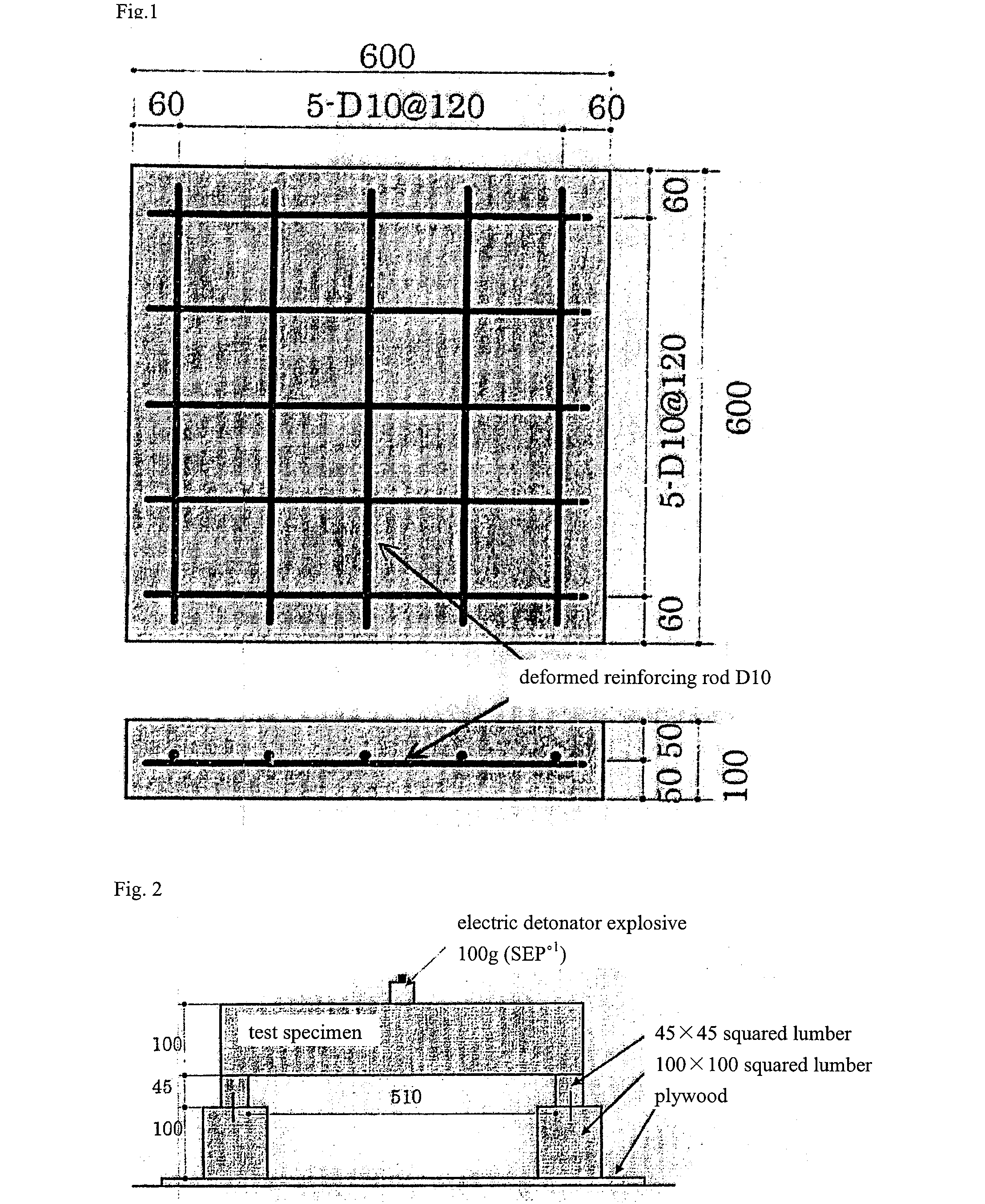
[0055]High molecular weight polyethylene fibers (DYNEEMA (registered trade mark) produced by TOYOBO Co., Ltd.) of 2640 dtex (fineness of a single fiber is 1.1 dtex) were covered with multiple turns of 230 turn / m of a polypropylene thermally adhesive yarn (PYLEN (registered trade mark) produced by MRC PYLEN Co., Ltd.) of 760 dtex, and then a bundle of the polyethylene fibers was thermally set at 120° C. to obtain a yarn (fiber composite). The tensile strength of the above multifilament of 2640 dtex was 2.9 GPa, the tensile modulus of elasticity was 97 GPa, the tensile strength of the yarn was 1.9 GPa, and the tensile modulus of elasticity was 43 GPa. This yarn was cut into the length of 3 cm. A test specimen was prepared at the fiber mixing ratio of 2.0 vol. % using the composition shown in Table 1. The amount of explosive used in blasting was set at 100 g to perform a blasting test.

example 2

[0056]High molecular weight polyethylene fibers (DYNEEMA (registered trade mark) produced by TOYOBO Co., Ltd.) of 1320 dtex (fineness of a single fiber is 1.1 dtex) were impregnated with an epoxy resin and a bundle of the fibers impregnated with an epoxy resin was cured to obtain a yarn. Furthermore, the yarn was embossed to provide projections and depressions. The tensile strength of the above multifilament of 1320 dtex was 3.1 GPa, the tensile modulus of elasticity was 105 GPa, the tensile strength of the yarn was 2.3 GPa and the tensile modulus of elasticity was 48 GPa. In addition, the amount of the resin adhering to the yarn was 120% by weight. This yarn was cut into the length of 3 cm. A test specimen was prepared at the fiber mixing ratio of 4.0 vol. % using the composition shown in Table 1. The amount of explosive used in blasting was set at 100 g to perform a blasting test.

example 3

[0057]PBO fibers (ZYLON (registered trade mark) produced by TOYOBO Co., Ltd.) of 1110 dtex (fineness of a single fiber is 1.5 dtex) were covered with multiple turns of 150 turn / m of a polypropylene thermally adhesive yarn (PYLEN (registered trade mark) produced by MRC PYLEN Co., Ltd.) of 760 dtex, and then a bundle of the polyethylene fibers was thermally set at 120° C. to obtain a yarn. The tensile strength of the above multifilament of 1110 dtex was 5.9 GPa, the tensile modulus of elasticity was 218 GPa, the tensile strength of the yarn was 2.6 GPa, and the tensile modulus of elasticity was 85 GPa. This yarn was cut into the length of 3 cm. A test specimen was prepared at the fiber mixing ratio of 2.0 vol. % using the composition shown in Table 1. The amount of explosive used in blasting was set at 100 g to perform a blasting test.


PUM

PropertyMeasurementUnit
compressive strengthaaaaaaaaaa
tensile strengthaaaaaaaaaa

Abstract

This invention provides a concrete having excellent exploding resistance, comprising a fiber as one constituent material, wherein said concrete has a compressive strength of 50 N / mm2 or more, a bending strength of 6 N / mm2 or more, and a ratio of the bending strength to the compressive strength is 15 or less. Upon explosion of an explosive material near a structure, a part of the structure is separated by explosion energy. In general, the separation of the structure on the side opposite to the side facing explosion is larger than that of the side facing explosion, it could trigger collapse of concrete, and the separation on this side has a larger risk of injuring persons within the structure. Since the present invention has the effect of reducing a separated volume, it can be used for various structures as a concrete for lifesaving or for preventing the collapse of the structure.

Description

REFERENCE TO RELATED APPLICATIONS[0001]This application is a national stage application under 35 USC 371 of International Application No. PCT / JP2007 / 059181, filed Apr. 27, 2007, which claims the priority of Japanese Patent Application No. 2006-125720, filed Apr. 28, 2006, the contents of which prior applications are incorporated herein by reference.FIELD OF THE INVENTION[0002]The present invention relates to a concrete having excellent exploding resistance for the purpose of preventing the destruction of concrete members by blasting of explosives, for example, preventing the collapse of structures by blasting or rocket bomb by the acts of terrorism targeting public structures, and further for the purpose of saving lives of persons within the structures.BACKGROUND OF THE INVENTION[0003]In recent years, disputes break out around the world because of confrontations among nations, between the religions, or between races, and measures such the destruction of a structure by blasting by th...

Claims


Application Information

Patent Timeline
Patent Type & Authority Applications(United States)
IPC IPC(8): B32B13/02C04B32/00B32B7/02
CPCC04B28/04C04B2111/00974C04B2201/50E04H9/10Y10T428/24942C04B14/06C04B16/0625C04B16/0691C04B18/084C04B18/105C04B18/144C04B18/22C04B2103/304Y02W30/91
Inventor KONISHI, TAKUYAMAEDA, TOKUICHIKAMIYAMA, KIYOSUKE
Owner TOYOBO CO LTD
Why Eureka
Try Eureka