Actuator control device and method

a technology of actuator control and control device, which is applied in the direction of valve operating device/release device, process and machine control, instruments, etc., can solve the problems of process control errors, inability to take the valve off line or shut it down, and increased down tim

Active Publication Date: 2012-05-03
TAPCOENPRO
View PDF4 Cites 45 Cited by
  • Summary
  • Abstract
  • Description
  • Claims
  • Application Information

AI Technical Summary

Benefits of technology

[0006]Provided is a device for controlling an actuator. An input interface receives a plurality of input signals. The input signals include a setpoint command signal and a feedback signal. An output interface provides a drive signal to the actuator. A first redundant loop controller processes the setpoint command signal and the feedback signal to generate a first actuator control signal. A second redundant loop controller processes the setpoint command signal and the feedback signal to generate a second actuator control signal. A third redundant loop controller processes the setpoint command signal and the feedback signal to generate a third actuator control signal. A primary controller compares the first actuator control signal, the second actuator control signal, and the third actuator control signal to determine whether at least one of the actuator control signals is substantially similar to another of the actuator control signals. The device outputs the drive signal to the actuator according to the at least one of the actuator control signals that has been determined by the primary controller to be substantially similar to another of the actuator control signals. Any one of the first redundant loop controller, the second redundant loop controller, and the third redundant loop controller is hot swappable with a replacement loop controller such that loop controller redundancy is operatively maintained by the device in controlling the actuator while one of the redundant loop controllers is hot swapped.
[0007]Further provided is a device for controlling an actuator. An input interface receives a plurality of input signals. The input signals include a setpoint command signal and a feedback signal. An output interface provides a drive signal to the actuator. A first redundant loop controller processes the setpoint command signal and the feedback signal to generate a first actuator control signal. A second redundant loop controller processes the setpoint command signal and the feedback signal to generate a second actuator control signal. A third redundant loop controller processes the setpoint command signal and the feedback signal to generate a third actuator control signal. A memory is associated with at least one of a primary controller, the first redundant loop controller, the second redundant loop controller, and the third redundant loop controller. The memory stores calibration parameters for processing the setpoint command signal and the feedback signal. The primary controller compares the first actuator control signal, the second actuator control signal, and the third actuator control signal to determine whether at least one of the actuator control signals is substantially similar to another of the actuator control signals. The device outputs the drive signal to the actuator according to the at least one of the actuator control signals that has been determined by the primary controller to be substantially similar to another of the actuator control signals. Any one of the first redundant loop controller, the second redundant loop controller, and the third redundant loop controller is hot swappable with a replacement loop controller. The device loads the calibration parameters for processing the setpoint command signal and the feedback signal from the memory into the replacement loop controller when one of the redundant loop controllers is hot swapped.
[0008]Further provided is a device for controlling an actuator. An input interface receives a plurality of inpu

Problems solved by technology

It might be inconvenient at the least, and possibly costly and undesirable, to take the valve off line or shut it down while the controller is repa

Method used


Image

  • Actuator control device and method
  • Actuator control device and method
  • Actuator control device and method

Examples


Embodiment Construction

[0014]The following description explains the invention in the context of a valve controller controlling a valve actuator and valve. However, it is to be appreciated that the disclosed controller need not be a valve controller and that the actuator need not be a valve actuator. The disclosed controller is suitable for controlling various types of actuators and positionable devices. Thus, the disclosed controller is not intended to be limited solely to valve control applications.

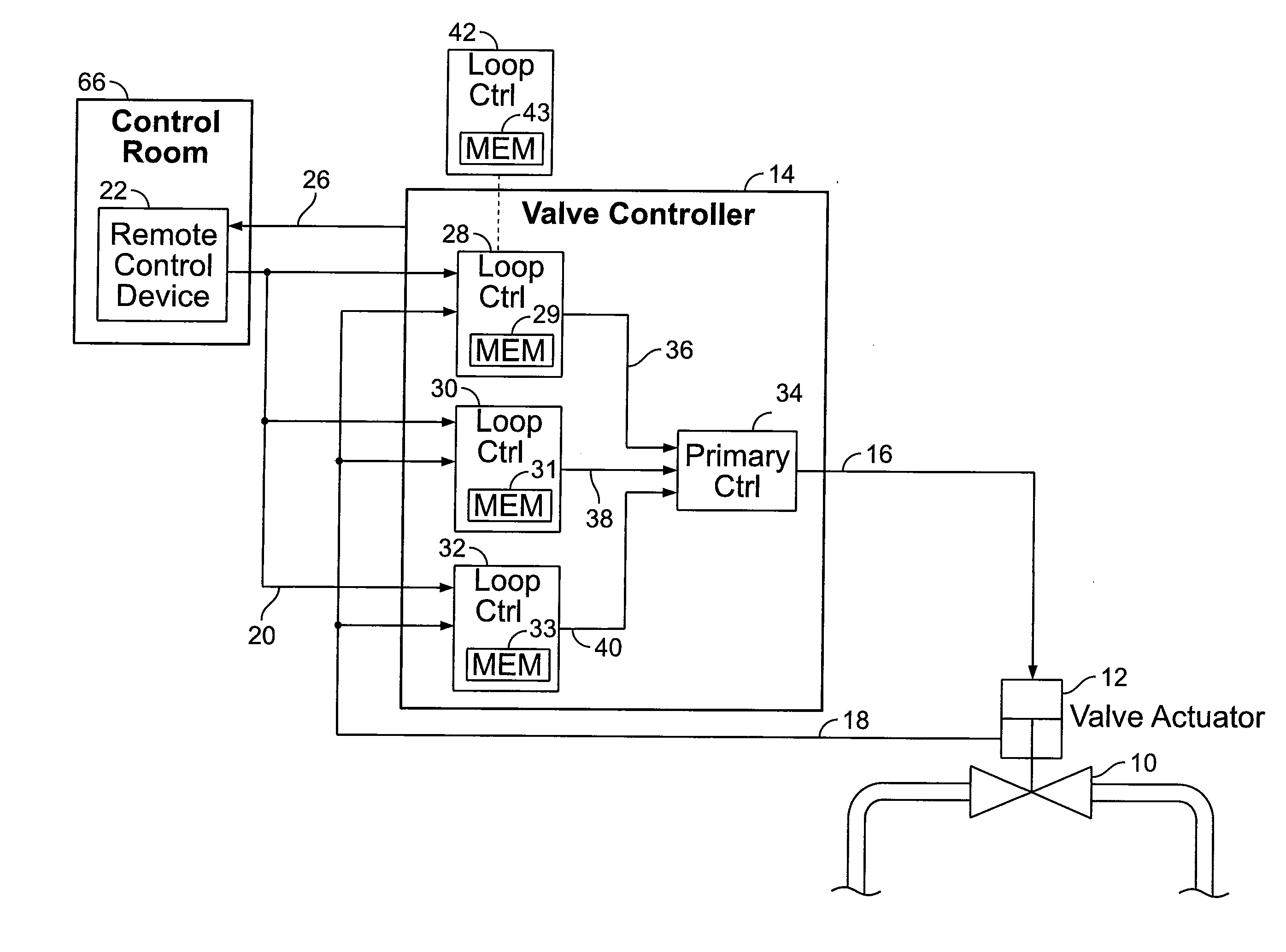
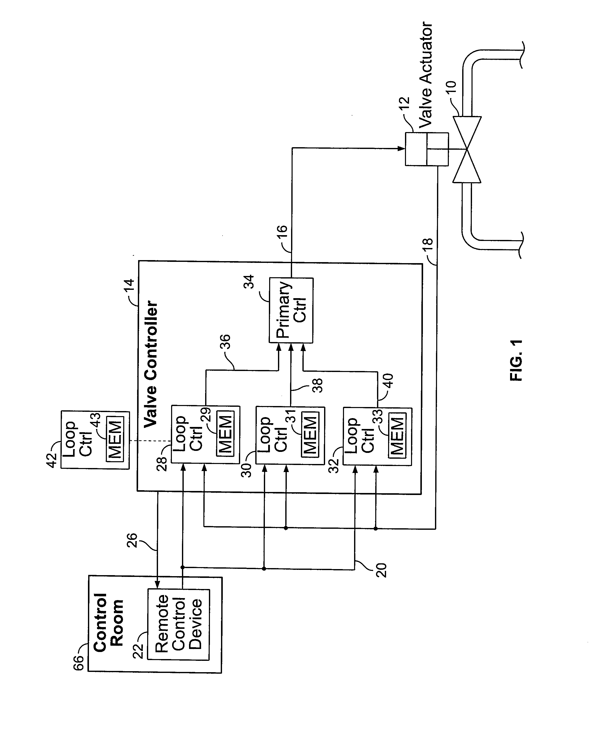
[0015]FIG. 1 is a high-level schematic block diagram of a device for controlling a valve 10 (e.g., slide, plug, butterfly, globe, gate, etc.) The valve 10 is positioned by an actuator 12. The actuator 12 in FIG. 1 is shown schematically as being a hydraulic actuator. However, the actuator 12 could be any type of actuator suitable for positioning a valve, such as a motorized actuator or a pneumatic actuator, for example.

[0016]A valve controller 14, such as a digital valve controller, provides a drive signal 16 ...


PUM


Abstract

A device for controlling an actuator includes an input interface that receives a plurality of input signals including a setpoint command signal and a feedback signal. An output interface provides a drive signal to the actuator. First, second, and third redundant loop controllers processes the setpoint command signal and the feedback signal to generate respective actuator control signals. A primary controller compares the actuator control signals to determine whether at least two are substantially similar. The device outputs the drive signal to the actuator according to an actuator control signals that has been determined by the primary controller to be substantially similar to another. Any one of the redundant loop controllers is hot swappable with a replacement loop controller such that loop controller redundancy is operatively maintained by the device in controlling the actuator while one of the redundant loop controllers is hot swapped.

Description

CROSS-REFERENCE TO RELATED APPLICATIONS[0001]Benefit of U.S. Provisional Patent Application Ser. No. 61 / 408,142 filed Oct. 29, 2010, is hereby claimed and the disclosure incorporated herein by reference.BACKGROUND OF THE INVENTION[0002]1. Field of the Invention[0003]The present invention relates to controllers for controlling actuators and / or valves. An example of such a controller is a digital valve controller that is programmable and controls an associated valve actuator based on various calibration parameters and input signals. The valve actuator, in turn, controls the position of a valve.[0004]2. Description of Related Art[0005]In conventional valve controllers, repairing a failed loop controller typically requires the normal operation of the valve to be interrupted. For example, the valve would be taken off line or otherwise shut down while its controller is repaired. Repairing the loop controller often involves a recalibration process, which can require fully stroking the valv...

Claims


Application Information

Patent Timeline
IPC IPC(8): F16K31/02G05B9/03
CPCG05B9/03Y10T137/0402
Inventor DO, DAN NGUYENMORELAND, ROBERT STOCKER
Owner TAPCOENPRO
Why Eureka
Try Eureka