Axial motor

a technology of axial motor and axial motor, which is applied in the direction of dynamo-electric machines, magnetic circuit rotating parts, magnetic circuit shape/form/construction, etc., can solve the problems of high cost, large size, and high axial motor enlargement, so as to achieve higher torque, higher efficiency, and high output

Inactive Publication Date: 2012-05-03
HOKKAIDO UNIVERSITY +1
View PDF18 Cites 23 Cited by
  • Summary
  • Abstract
  • Description
  • Claims
  • Application Information

AI Technical Summary

Benefits of technology

[0012]The present invention was developed in view of the above situation and an object thereof is to provide an axial motor capable of achieving a higher output (higher torque) and higher efficiency (miniaturization).

Problems solved by technology

Such an axial motor has a problem that torque pulsation (cogging torque) is likely to occur.
Thus, if a desired torque is large, the volume of the axial motor increases, leading to a problem of size enlargement.
Further, cost also increases as the axial motor becomes larger.

Method used


Image

  • Axial motor
  • Axial motor
  • Axial motor

Examples


Embodiment Construction

[0024]Hereinafter, an embodiment according to the present invention is described with reference to the drawings. Note that constructions identified by the same reference numerals in the respective drawings are identical and not repeatedly described.

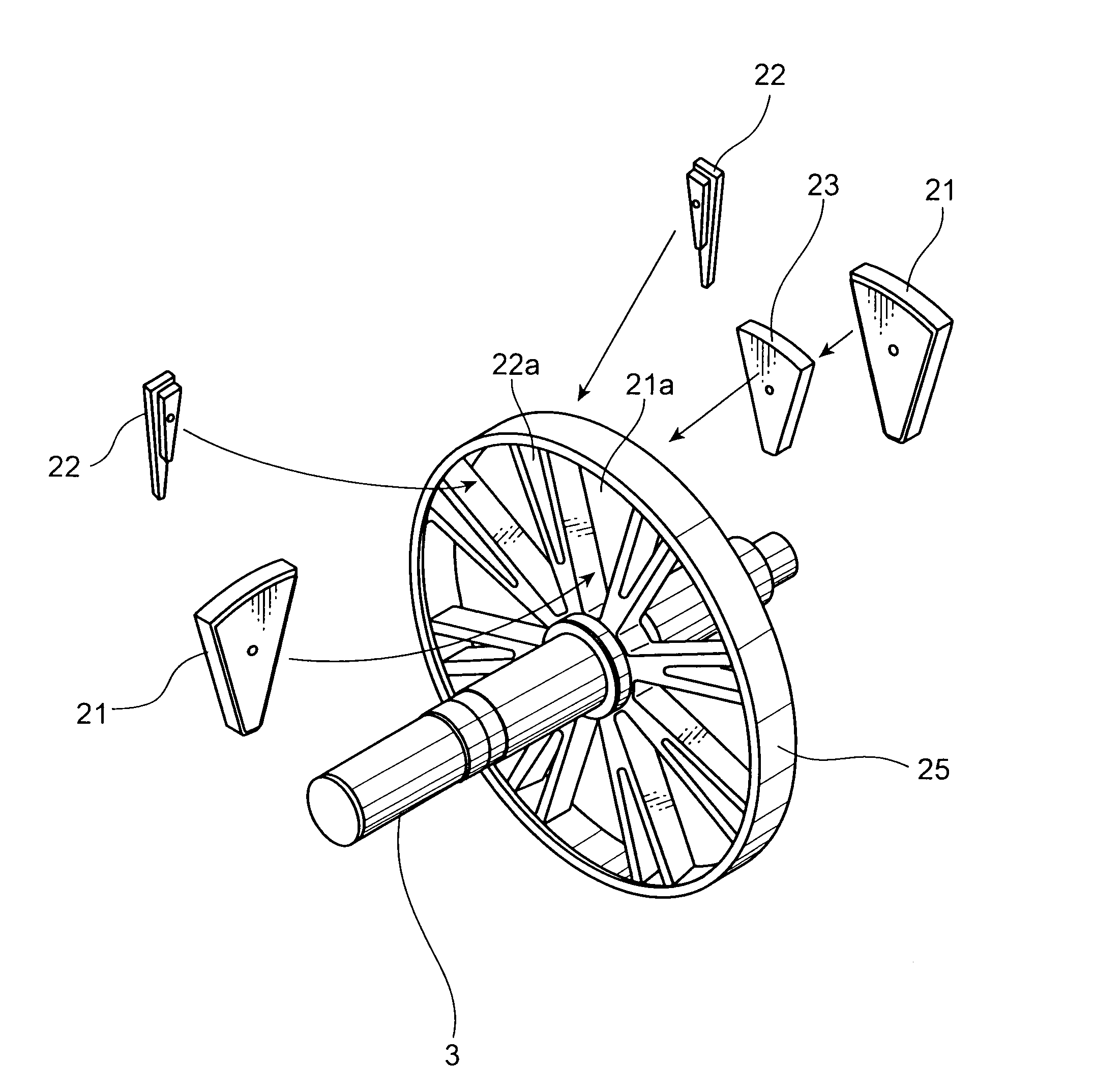
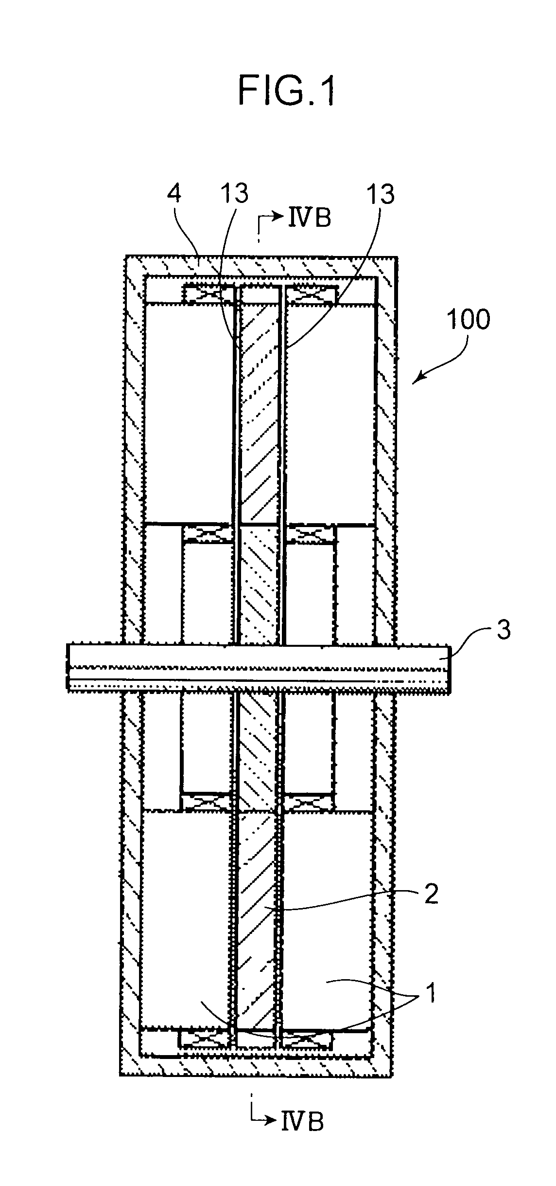
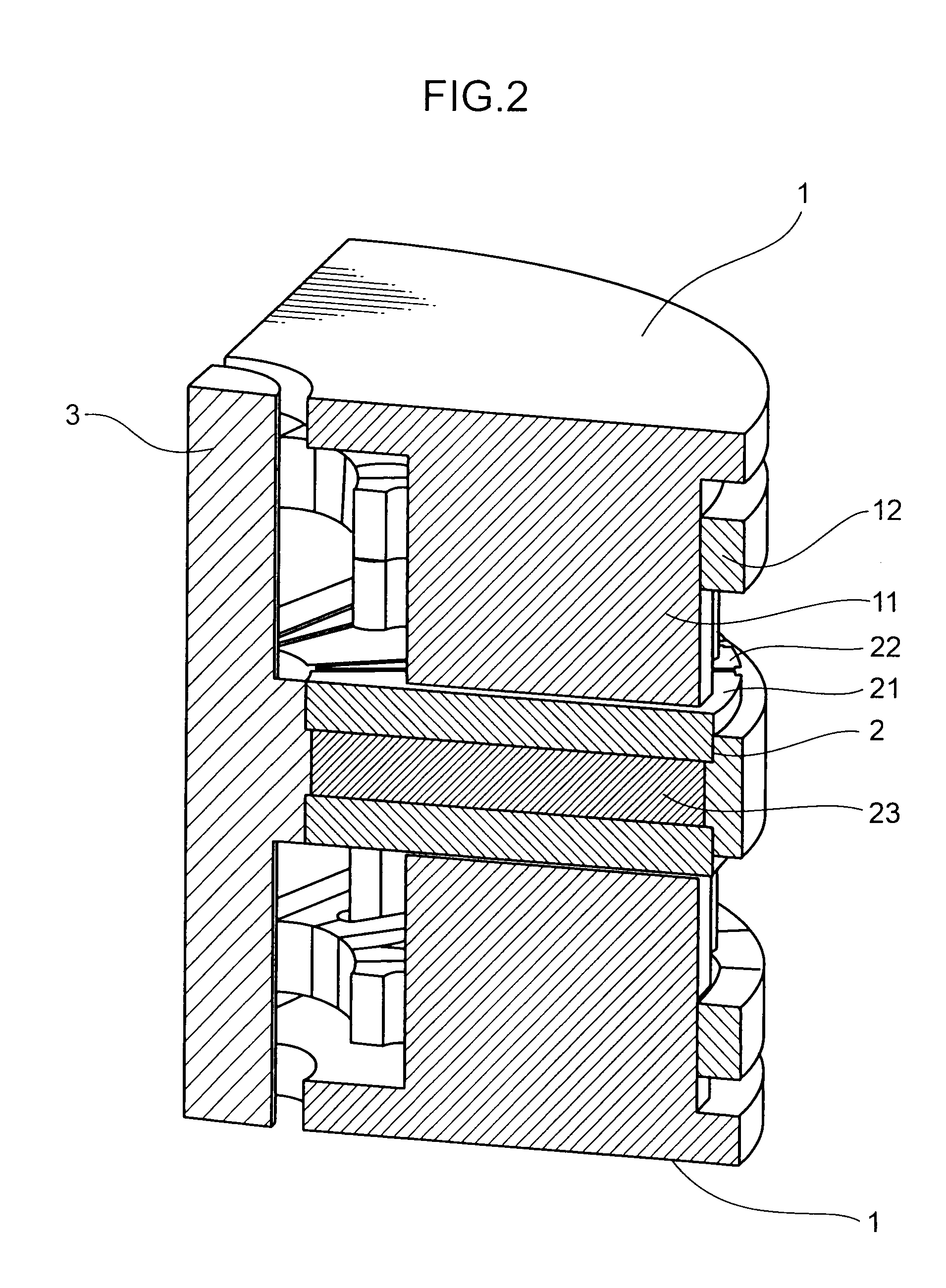
[0025]FIG. 1 is a schematic sectional view showing the construction of an axial motor according to this embodiment. FIG. 2 is a perspective view partly in section of the axial motor according to this embodiment. Note that since the interior of a casing is shown in FIG. 2, the casing is not shown. Further, FIG. 2 is a sectional view of the axial motor along planes including a rotary shaft and perpendicular to each other. As shown in FIGS. 1 and 2, the axial motor 100 includes a disk-shaped rotor (rotor) 2 fixed to a rotary shaft 3 rotatably supported in a casing 4 and a pair of stators (stators) 1 disposed to sandwich the rotor 2 from front and rear sides of the rotor 2. Note that the front and rear sides of the rotor 2 are sides toward th...


PUM


Abstract

An axial motor includes a rotor arranged between a pair of stators with coils. In the rotor, a plurality of permanent magnets sandwiched between pairs of first magnetic materials and a plurality of second magnetic materials are alternately arranged in a rotation direction while gaps are provided therebetween. Since the permanent magnets are sandwiched by the first magnetic materials in the thus constructed axial motor, a field-weakening control can be performed. Since the second magnetic materials are provided, a reluctance torque can be generated. Further, since the gaps are provided, more magnetic fluxes generated from the permanent magnets can be caused to flow toward the coils. Therefore, the thus constructed axial motor can achieve a higher output, higher torque, higher efficiency, and miniaturization.

Description

TECHNICAL FIELD[0001]The present invention relates to an axial motor in which magnetic poles of stators and permanent magnets disposed on a rotor are arranged to face each other in directions parallel to a rotary shaft.BACKGROUND ART[0002]There has been known an axial motor constructed such that magnetic poles of stators and permanent magnets disposed on a rotor are arranged to face each other in directions parallel to a rotary shaft. Such an axial motor has advantages that miniaturization is possible and also an output can be increased. Thus, the axial motor is used in various applications.[0003]The axial motor is constructed, for example, as disclosed in patent literatures 1 and 2. More specifically, the axial motor includes a rotor having a plurality of fan-shaped permanent magnets arranged in an annular manner on the surface of an iron core made of soft iron or the like, and stators with coils which form magnetic poles facing these permanent magnets in directions parallel to a r...

Claims


Application Information

Patent Timeline
Patent Type & Authority Applications(United States)
IPC IPC(8): H02K16/04
CPCH02K1/2793H02K21/24H02K1/2796H02K16/04H02K1/27
Inventor TAKEMOTO, MASATSUGUMITANI, HIROYUKIHOJO, HIROFUMIINOUE, KOJIOZAKI, OSAMU
Owner HOKKAIDO UNIVERSITY
Why Eureka
Try Eureka