Camera mounting assembly

a technology for mounting assemblies and cameras, applied in the manufacture of electrolytic capacitors, capacitor dielectric layers, instruments, etc., can solve the problems of prone to tipped over or tipped over camera, prone to multiple parts, and inability to easily transport, so as to facilitate easy fastening of the members together and stable balance

Active Publication Date: 2012-05-03
REALLY RIGHT STUFF
View PDF5 Cites 43 Cited by
  • Summary
  • Abstract
  • Description
  • Claims
  • Application Information

AI Technical Summary

Benefits of technology

[0007]In a first aspect of the invention, a camera mounting assembly is provided including a base member and a side member. The base member has an upper portion configured to support a lower surface of the camera and a lower portion forming an opposite pair of lower slots. The side member forms an opposite pair of side slots. The assembly further includes a fastening element configured to detachably fasten together the side member and the base member such that when the lower surface of the camera is supported by the base member, at least a portion of the side member is aligned with a side surface of the camera and such that a pair of moveable jaws of the quick-release mechanism are selectively engageable with the lower slots and side slots to adjustably mount the camera in a landscape orientation and a portrait orientation, respectively, while maintaining the camera in a generally centered position over the vertical support. The detachable construction of the members permits a user to purchase the base and side members at separate times as their budget allows while the slots formed in the members enable quick mounting of the camera either in the landscape or portrait orientation while the camera is stably balanced over the vertical support.
[0008]In a second aspect of the invention, a camera mounting assembly is provided including a base member and a side member. The base member has an upper portion configured to receive a lower surface of the camera and a lower portion, the lower portion being adapted for selective mounting on the vertical support such that the camera is positioned in a landscape orientation. The side member is detachably fastenable to the base member such that at least a portion of the side member extends along a side surface of the camera received by the base member, the side member form

Problems solved by technology

However, when the camera is pivoted about the ball joint to the portrait orientation, the weight of the camera and carrier are off kilter from the central axis of the camera support, thereby making the vertical support prone to being tipped over or making the camera more susceptible to environmental factors such as wind drafts.
Furthermore, if the camera is being used for close-up shots, the camera lens is significantly displaced along the vertical and horizontal directions during repositioning so that the vertical suppor

Method used


Image

  • Camera mounting assembly
  • Camera mounting assembly
  • Camera mounting assembly

Examples


Embodiment Construction

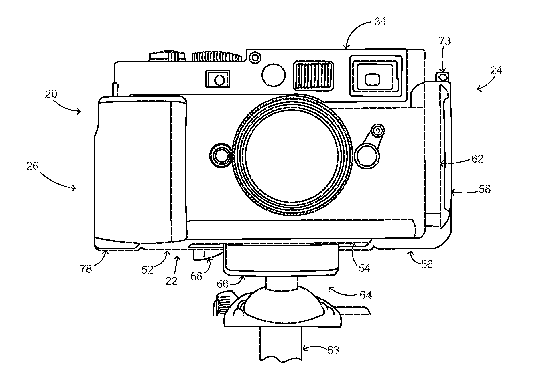
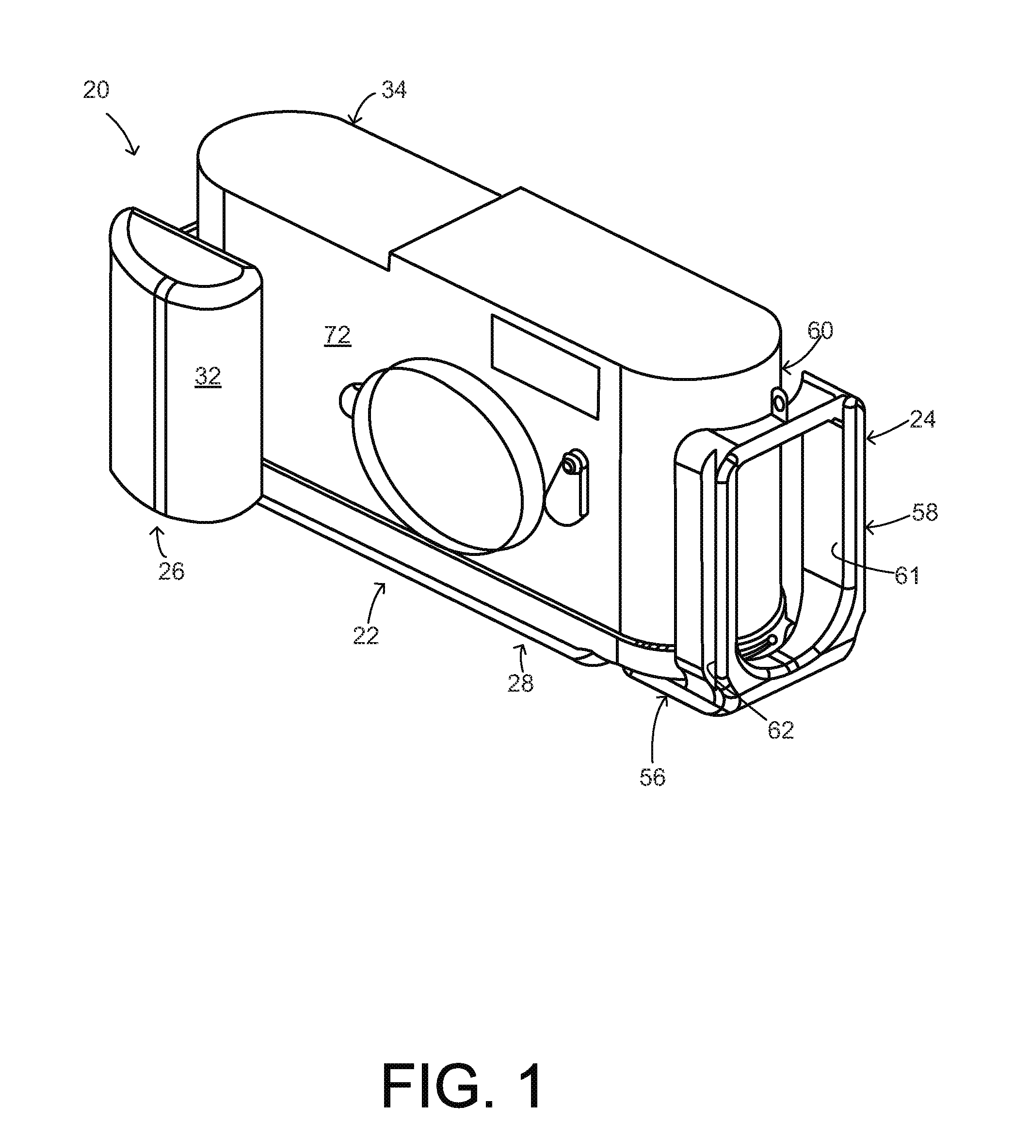
[0030]FIG. 1 shows a camera mounting assembly 20 that when fully configured as shown, includes a base member or plate 22, an L-shaped side member or plate 24, and a second camera accessory 26. The side member and second accessory are detachably fastened to a lower portion 28 of the base plate, preferably at lower corner portions 30a and 30b depicted in FIG. 7. The second camera accessory may be configured as a hand grip 32 as shown. As further discussed below, the modular and compact construction depicted enables adjustable mounting of a conventional camera 34 on a vertical support in a manner compatible with convenient purchase, transport, and reconfiguration of the assembly.

[0031]The various pieces of the assembly 20 of FIG. 1 are each precision machined in a computed numerically controlled (CNC) process from aluminum stock for a well-fitted, durable, and lightweight construction. Each piece is anodized satin black to match the camera finish.

[0032]FIG. 3 shows the camera 34 being ...


PUM


Abstract

A camera mounting assembly includes a base member or plate for holding a camera and a side member or plate. In an exemplary embodiment, lower slots on the base plate or side slots on the side plate are gripped by a vertical support's quick-release mechanism to mount the camera in a landscape or portrait orientation, respectively, the camera being generally centered and evenly balanced over the support in either case. The side member is detachably fastened to the base member, which modular construction permits separately timed purchase of the base member and side member as allowed by the user's budget and further permits breakdown of the assembly for ease of transport. The side member may be generally L-shaped with a lower arm length less than the side arm length, which also facilitates transport. Other components may be detachably added such as a hand grip facilitating freehand shooting with the camera.

Description

CROSS-REFERENCE TO RELATED APPLICATIONS[0001]This application claims the benefit of U.S. Provisional App. No. 61 / 409,884, filed Nov. 3, 2010.TECHNICAL FIELD[0002]This invention relates to a camera mounting assembly for mounting a camera on a vertical support, such as a stand or tripod. In particular, the invention relates to a mounting assembly for adjustably mounting the camera on the vertical support in different orientations.BACKGROUND OF THE INVENTION[0003]It is known in the art to provide a vertical camera support including a support platform having a quick-release mechanism, such as one manufactured by ARCA-Swiss Phototechnik AG. This quick-release mechanism has opposed jaws selectively moveable to a clamping position for selectively gripping slots that are formed in a carrier holding the camera. The mounting mechanism may include a turnable thumb screw or pivoting lever for moving and securing the jaws in the clamping position. This allows the camera to be quickly mounted on ...

Claims


Application Information

Patent Timeline
IPC IPC(8): G03B17/56
CPCG03B17/561G03B17/563F16M11/08G03B17/56H01G9/0032H01G9/0036H01G9/025H01G9/0425H01G9/07H01G9/15
Inventor JOHNSON, JOSEPH M.
Owner REALLY RIGHT STUFF
Why Eureka
Try Eureka