

Protective cap for a connector
- Summary
- Abstract
- Description
- Claims
- Application Information
AI Technical Summary
Benefits of technology
Problems solved by technology
Method used
Image

Examples
first embodiment
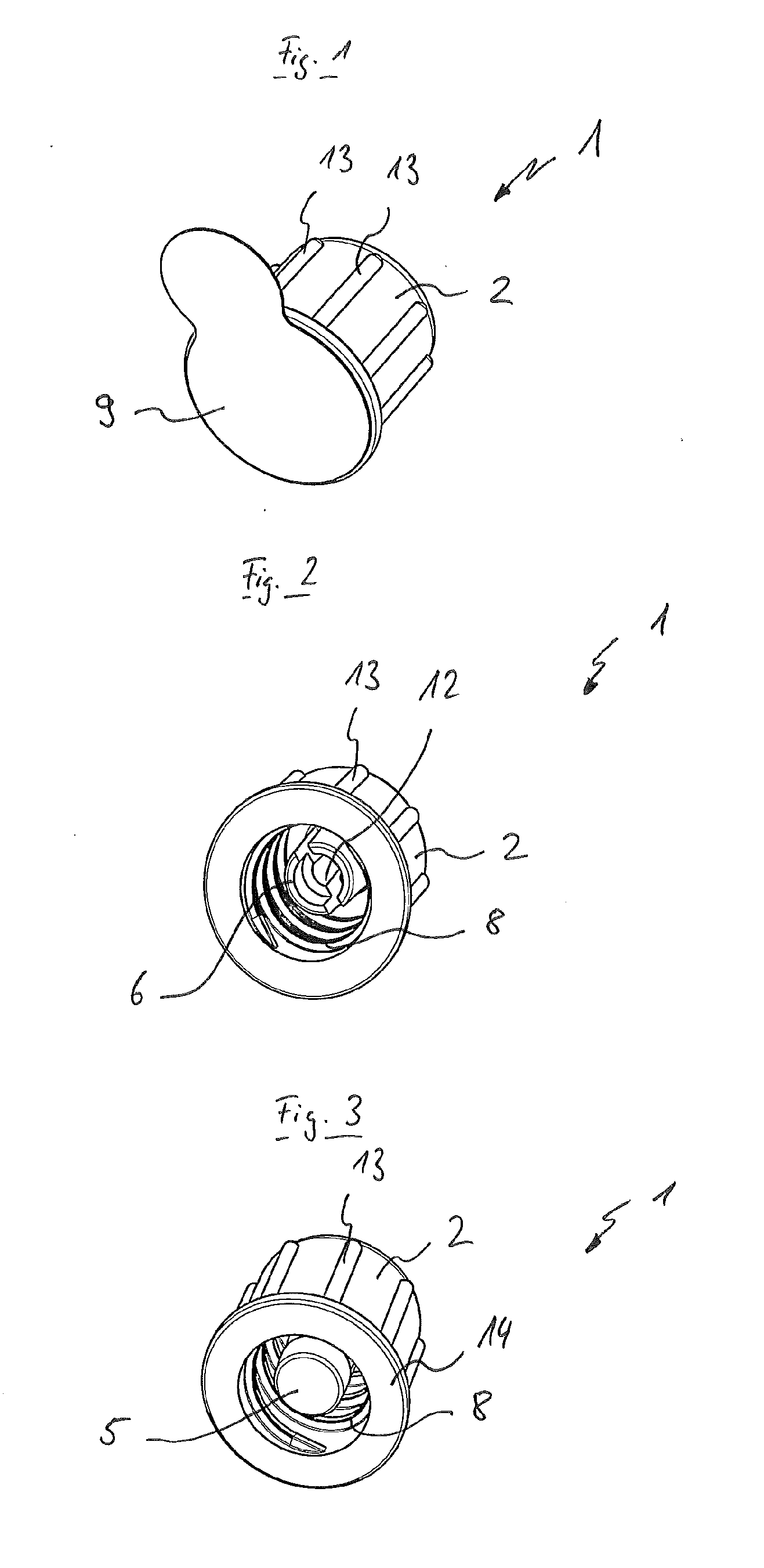
[0018]FIG. 1 A perspective view of a protective cap according to the invention,
[0019]FIG. 2 A view of the protective cap shown in FIG. 1, in which the swab has been left out,
[0020]FIG. 3 A view of the protective cap shown in FIG. 1, with the swab,
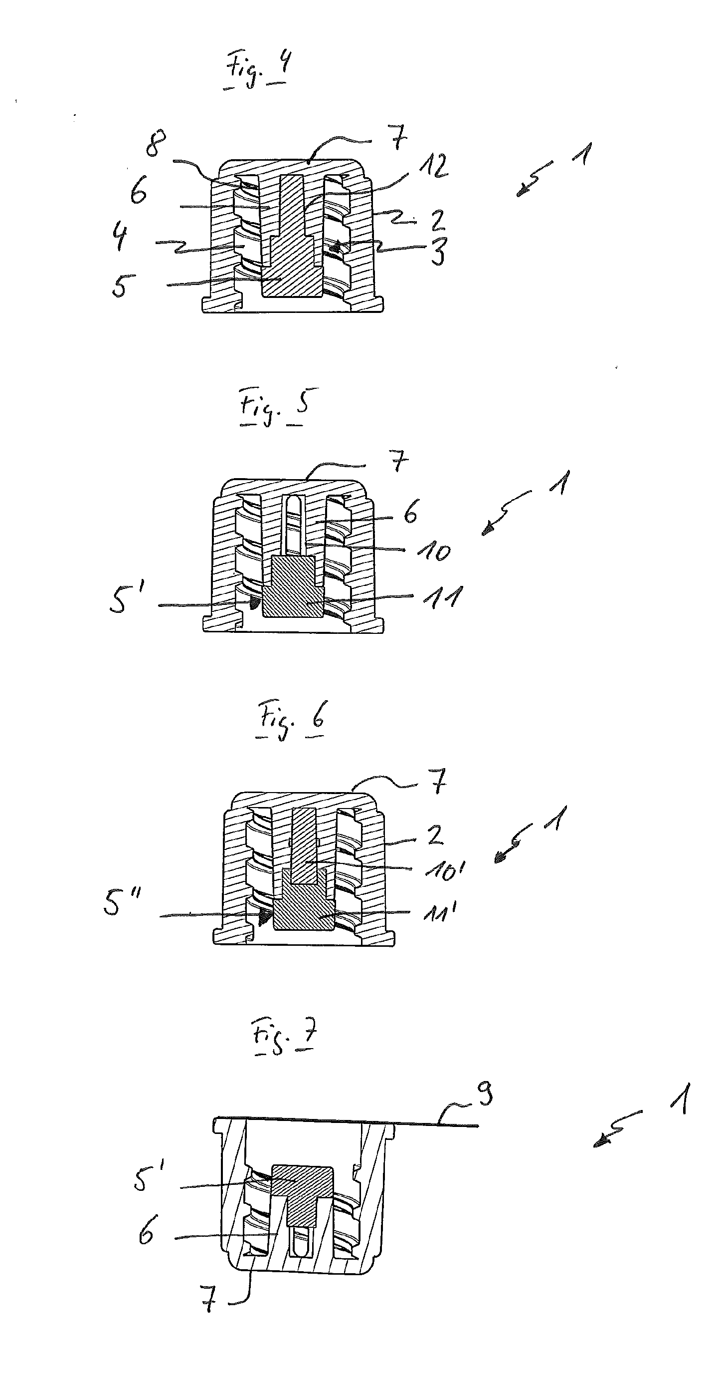
[0021]FIG. 4 A cut-away illustration of the protective cap with a first swab,
[0022]FIG. 5 A cut-away illustration of the protective cap with a second swab,
[0023]FIG. 6 A cut-away illustration of the protective cap with a third swab,
[0024]FIG. 7 A cut-away illustration of the protective cap with the second swab and a barrier film
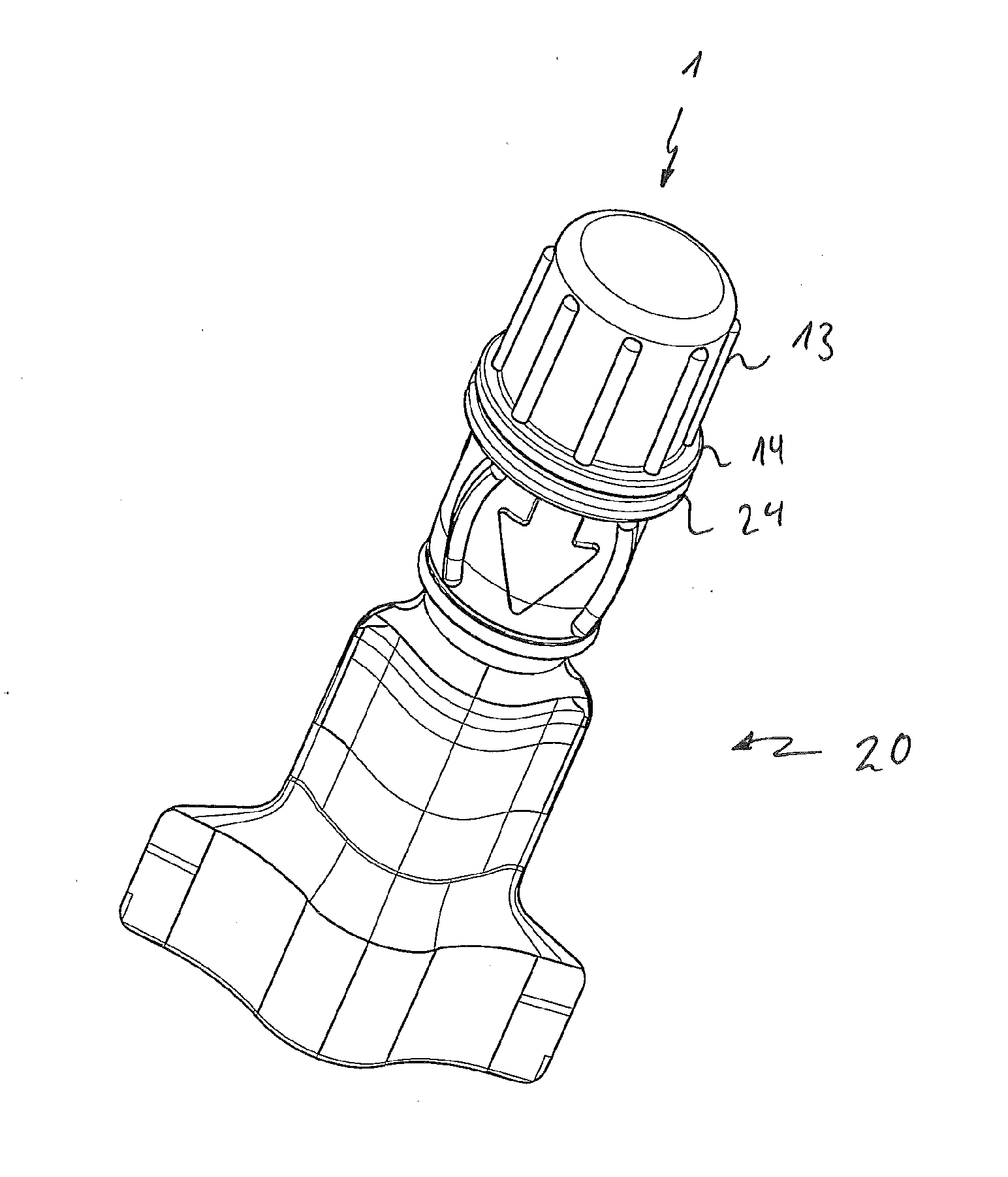
[0025]FIG. 8 A perspective view of a connector system with a protective cap according to a first embodiment, and a connector,
[0026]FIG. 9 A longitudinal cut through the connector system shown in FIG. 8,
second embodiment
[0027]FIG. 10 A perspective view of a protective cap,
[0028]FIG. 11 A further perspective view of the protective cap shown in FIG. 10,
[0029]FIG. 12 A perspective view of a connector system with a protective cap according to a second embodiment, and a connector, and
[0030]FIG. 13 A longitudinal cut through the connector system shown in FIG. 12.
PUM
 Abstract
Description
Claims
Application Information