Display device

a display device and display technology, applied in the field of display devices, can solve problems such as color shading, uniform luminance, and uniform luminance, and achieve the effect of preventing uniform luminance or color shading

Inactive Publication Date: 2012-05-10
HITACHI DISPLAYS
View PDF1 Cites 58 Cited by
  • Summary
  • Abstract
  • Description
  • Claims
  • Application Information

AI Technical Summary

Benefits of technology

[0015]According to the invention, in a display device in which the display area has an irregular hexagonal shape containing a display area sloping portion of a shape formed by cutting-off a corner from a rectangular shape, the size of the video signal line in the sou

Problems solved by technology

However, such a configuration is required to ensure a space therefor in addition to the display area and involves a p

Method used


Image

  • Display device
  • Display device
  • Display device

Examples


first embodiment

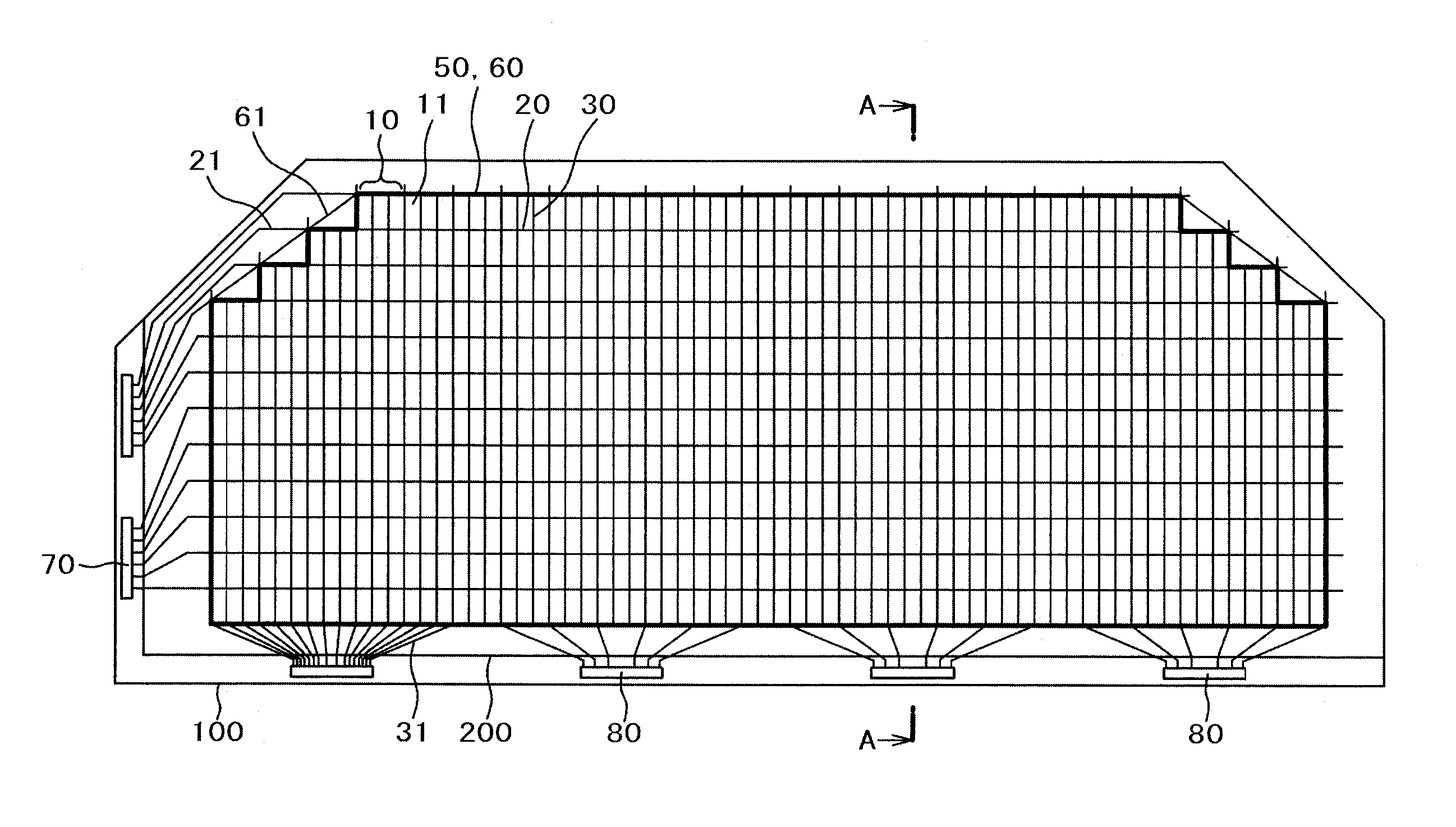
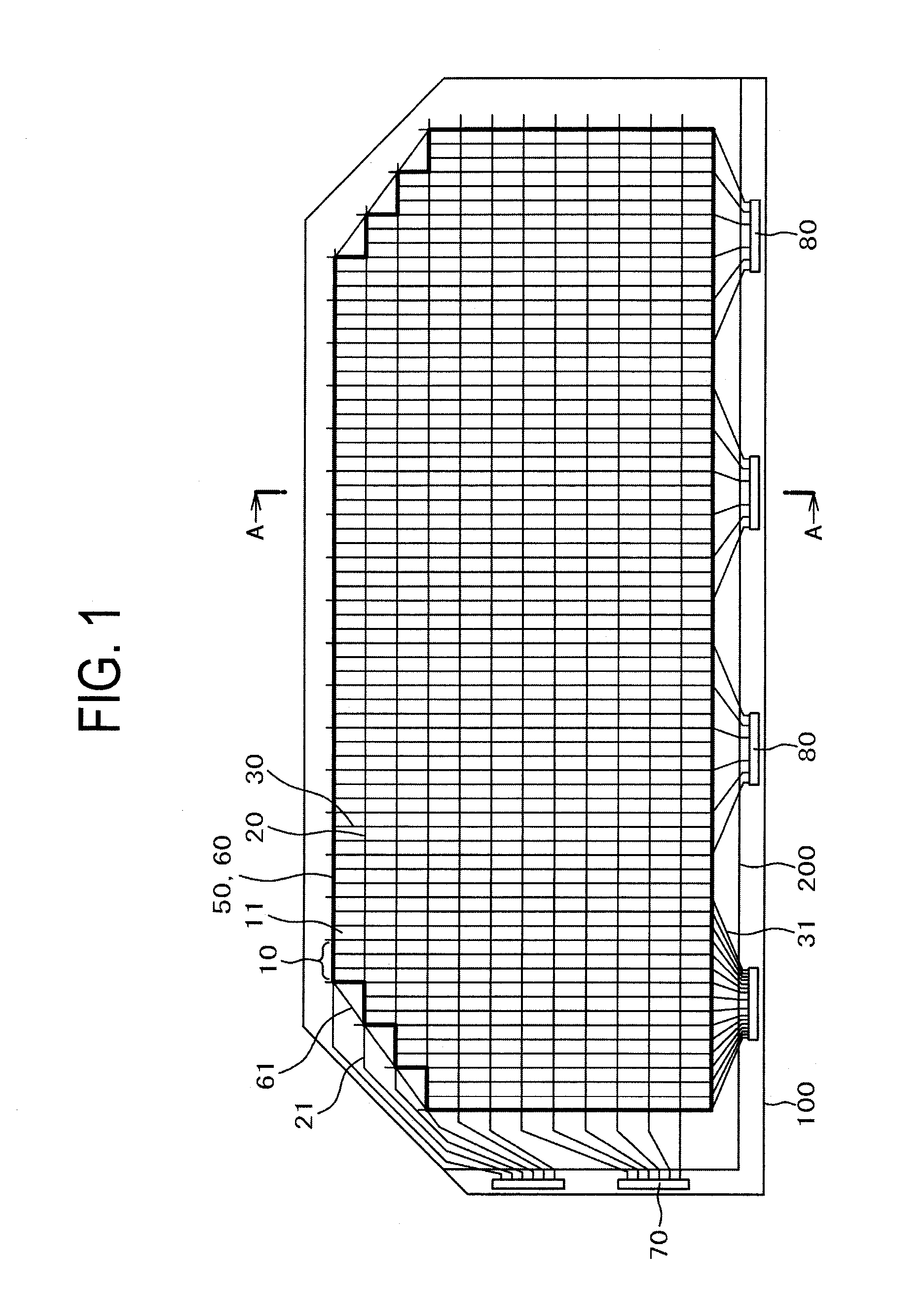
[0028]FIG. 1 is a plan view of a liquid crystal display device according to the present invention. The liquid crystal display device in FIG. 1 has a irregular hexagonal shape in which corners of a rectangle are cut-off. FIG. 2 is a cross-sectional view along line A-A in FIG. 1. In FIG. 1 or FIG. 2, a counter substrate 200 having color filters, etc. formed thereon is disposed over a TFT substrate 100 having pixels 10 formed in a matrix. A not illustrated liquid crystal layer is put between the TFT substrate 100 and the counter substrate 200.

[0029]In FIG. 1, the TFT substrate 100 is formed larger than the counter substrate 200, and gate drivers 70 for driving scanning lines 20 or source drivers 80 for driving video signal lines 30 are arranged at a portion in which the TRT substrate 100 is made larger than the counter substrate 200.

[0030]The scanning lines 20 are extended horizontally and arranged vertically in the display area 60. Further, the video signal lines 30 are extended verti...

second embodiment

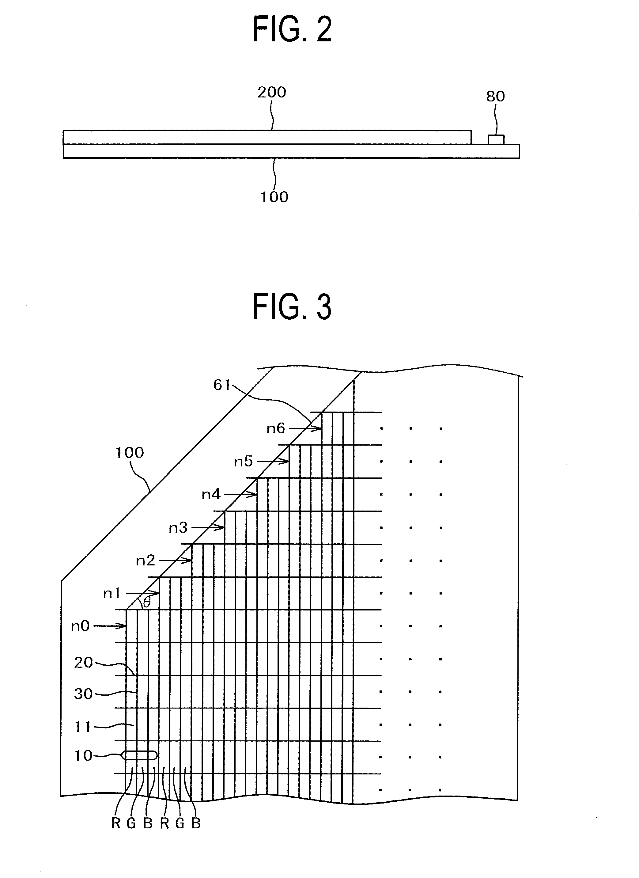
[0047]FIG. 8 is a plan view for a corner cut-off portion in a liquid crystal display device showing a second embodiment of the invention. FIG. 8 is an enlarged plan view of a display area sloping portion 61 in FIG. 1. The configuration in FIG. 8 is identical with that in FIG. 3 of the first embodiment except that the number of the sub-pixels is decreased for every six on each side of the display area and for every 12 on both sides in the display area.

[0048]That is, in FIG. 8, n0, n1, n2, etc. represent each the number of sub-pixels 11 in the horizontal direction on each side of the display area. n0 is a number of the sub-pixels in a full size display area in the horizontal direction on each side of the display area. Accordingly, n0−n1=6, n1−n2=6, n3−n2=6, etc. are satisfied. The shape of the pixel 10 is identical with that in FIG. 4.

[0049]FIG. 9 is a view in which only the video signals 30 in FIG. 8 are extracted. In FIG. 9, 1 p shows video signal lines for 1 pixel. As shown in FIG....

third embodiment

[0051]In the first or second embodiment, the pixel 10 comprises the three sub-pixels 11 and the shape of the pixel 10 is square as shown in FIG. 4. In the case of the first or second embodiment, the angle of inclination θ for the display area sloping portion 61 is defined as tan−1(yp / xp) or 1 / 2 tan−1(hp / xp), etc. Accordingly, it is difficult to cope with various inclined angles θ in the display area.

[0052]In this embodiment, the invention can cope with optional angle of inclination θ in the display area by changing the shape of the pixel 10 or the shape of the sub-pixel 11 conforming to the angle of inclination θ in the display area. FIG. 10 is a plan view for a corner cut-off portion in a liquid crystal display device showing a third embodiment of the invention. FIG. 10 is an enlarged plan view of the display area sloping portion 61 in FIG. 1.

[0053]In FIG. 10, the sub-pixel is decreased for every three on each side of the display area in the same manner as for the first embodiment ...


PUM


Abstract

Luminance ununiformity and color shading are prevented in a display area of an irregular hexagonal shape formed by cutting-off a corner from a rectangular shape.
Sub-pixels are formed in each of regions surrounded by scanning lines and video signal lines and a set of sub-pixels by the number of three define one pixel. The display area is an irregular hexagonal shape containing a display area sloping portion of a shape formed by cutting-off a corner from a rectangular shape. In the display area sloping portion, the number of sub-pixels in the extending direction of the scanning lines changes uniformly for every sub-pixels by the number of three or by the number of a multiple thereof on each side of the display area for one scanning line. The magnitude of the video signal in the source driver can be controlled easily by uniformly changing the number of the sub-pixels.

Description

CLAIM OF PRIORITY[0001]The present application claims priority from Japanese Patent Application JP 2010-249766 filed on Nov. 8, 2010, the content of which is hereby incorporated by reference into this application.BACKGROUND OF THE INVENTION[0002]1. Field of the Invention[0003]The present invention relates to a display device and particularly relates to a display device having an outer profile modified from a rectangular shape to an irregular shape so as to conform to a display device of a special shape.[0004]2. Description of the Related Art[0005]A liquid crystal display panel used in a liquid crystal display device includes a TFT substrate, a counter electrode opposing the TFT substrate, and liquid crystals put between the TFT substrate and the counter substrate. The TFT substrate has pixels including pixel electrodes, thin film transistors (TFT), etc. formed thereon in a matrix form. The counter electrode has color filters, etc. formed at positions corresponding to the pixel elect...

Claims


Application Information

Patent Timeline
IPC IPC(8): G09G3/36G09G3/30
CPCG02F1/134309G02F2201/56G09G3/3225G09G2380/10G09G2300/0426G09G2320/0223G09G2320/0233G09G3/3648G02F1/133G02F1/1345G09G3/36
Inventor NAKANISHI, NORIOIGETA, KOICHI
Owner HITACHI DISPLAYS
Why Eureka
Try Eureka