
Anti-trip device for an escape mechanism

an anti-trip device and escape mechanism technology, applied in the direction of escapements, frequency stabilisation mechanisms, instruments, etc., can solve the problems of large thickness, complex mechanism, and increased complexity of detent escapements in wristwatches, and achieve the effect of easy adaptation

Active Publication Date: 2012-05-10
NIVAROX FAR
View PDF5 Cites 7 Cited by
  • Summary
  • Abstract
  • Description
  • Claims
  • Application Information

AI Technical Summary

Benefits of technology

The invention proposes an anti-trip device for escape mechanisms that is simple, reliable, inexpensive, and easy to adapt to existing escape mechanisms. The device includes a banking pin fixed to a plate, a rotor fixed to a balance, and a bistable lever pivoted about a second pivot axis. The bistable lever includes a first lever arm and a second lever arm that correspond to different indexing positions. The device also includes amplitude limiting means to prevent excessive shocks and first and second stop means to prevent interference with the balance. The invention also concerns an escape mechanism for a timepiece movement and a timepiece including the escape mechanism.

Problems solved by technology

The use of detent escapements in wristwatches is more complex, because of the sensitivity of such escapements to shocks.
This mechanism is complex, relatively expensive and extends over several planes, which gives it significant thickness.
The moveable bridge may also be dampened by a dampening system which dissipates part of the energy due to the shock.
Part of the energy from the barrel is, however, consumed in friction during the sliding phase.
In short, known embodiments are often complex and difficult to adapt from one escape mechanism to another.
The method of stopping the balance is generally very abrupt and does not always ensure that the movement will restart without intervention.

Method used


Image

  • Anti-trip device for an escape mechanism
  • Anti-trip device for an escape mechanism
  • Anti-trip device for an escape mechanism

Examples


Embodiment Construction

[0045]The invention concerns the field of horology.

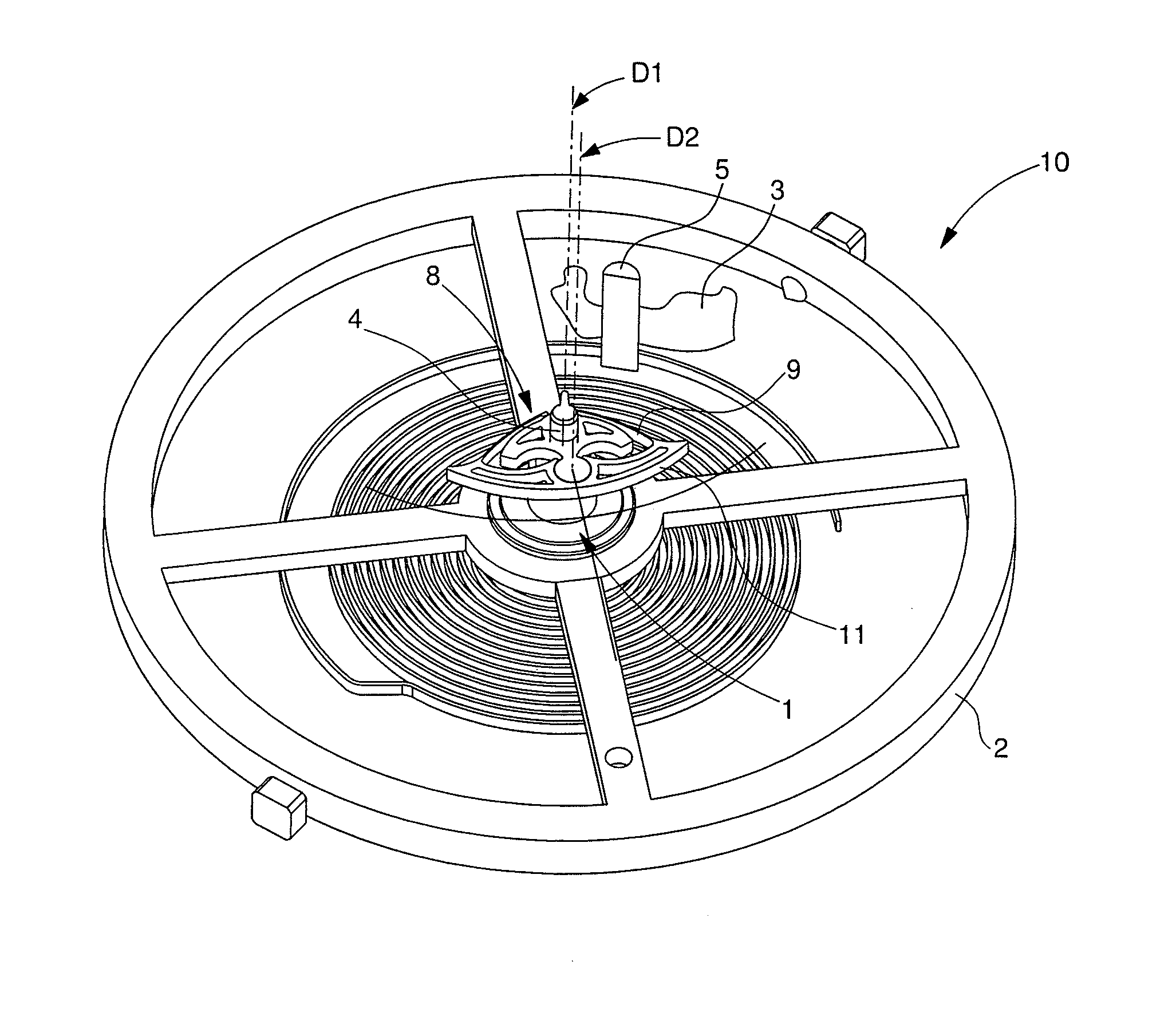
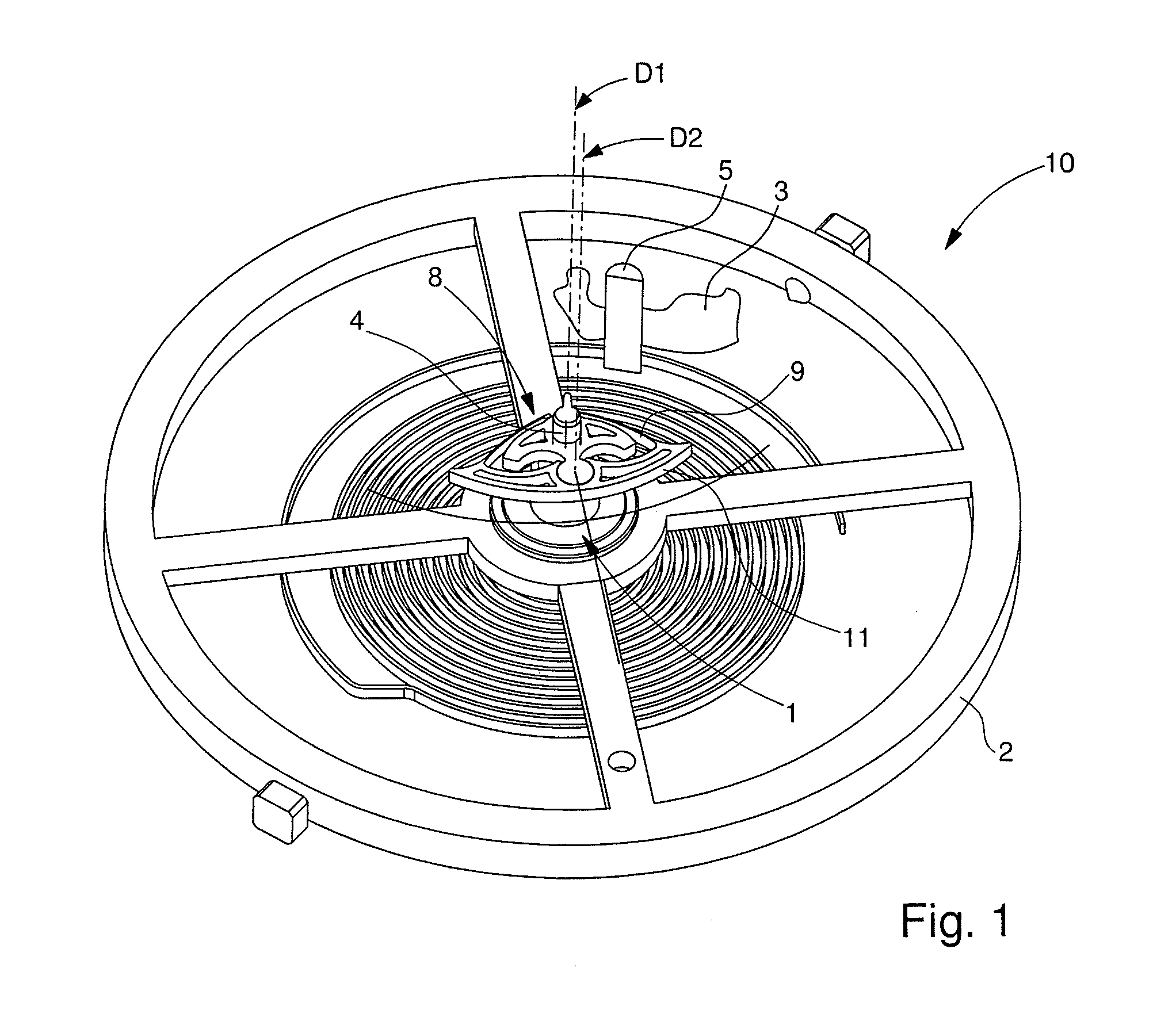
[0046]The invention concerns an anti-trip device 1 for an escape mechanism 10. This anti-trip mechanism 1 is arranged to cooperate with a balance 2, which pivots about a first pivot axis D1, whose position is fixed relative to a plate 3.

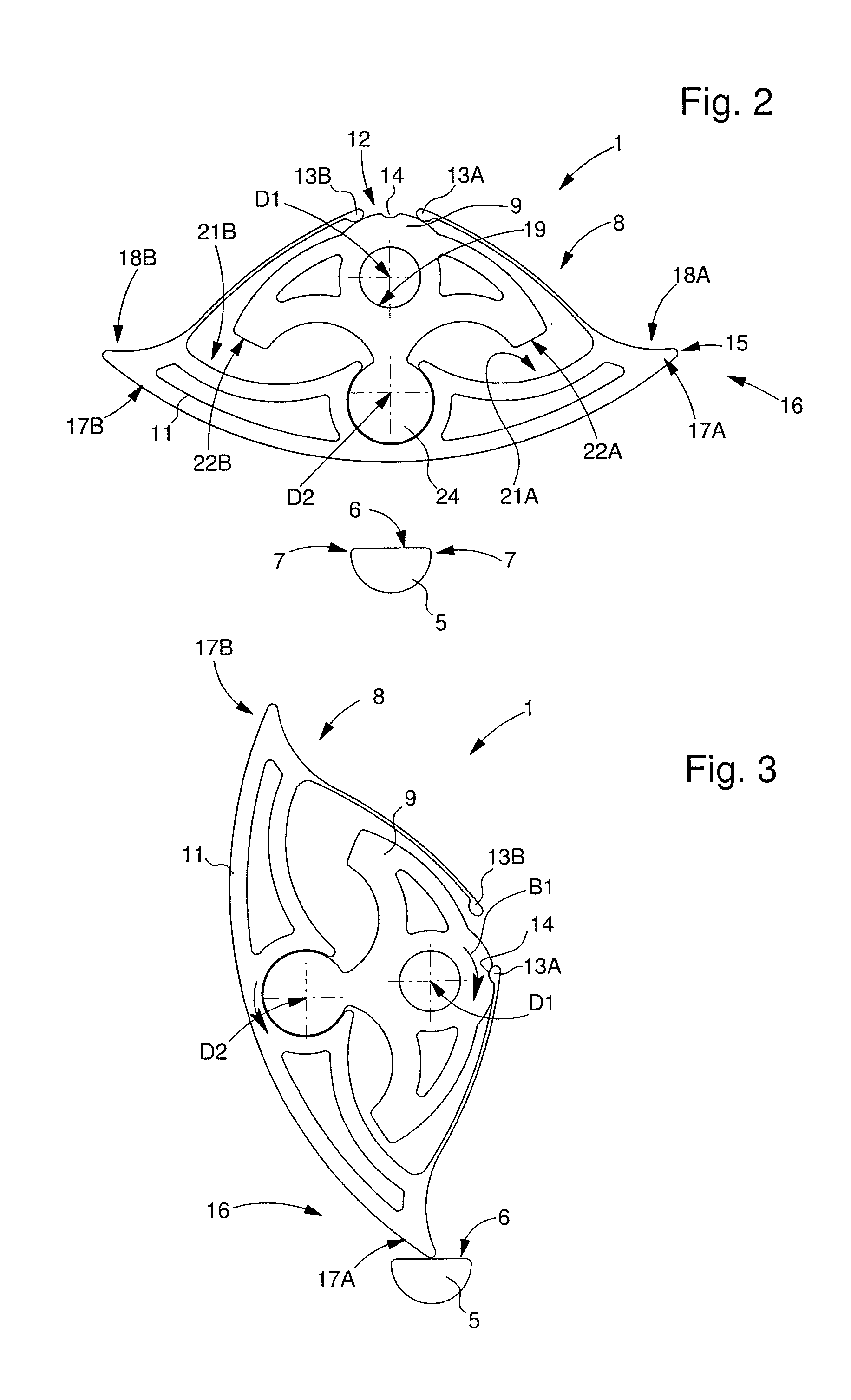
[0047]Anti-trip device 1 according to the invention is very simple, since it is formed of a maximum of three components: a banking pin 5 fixed to the plate of the escape mechanism, or of the movement, or of the timepiece, a rotor 9 fixed to the balance 2 and a bistable lever 11. It will be seen hereinafter that, in a particular version, it may be reduced to two components.

[0048]Thus, according to the invention, device 1 includes a banking pin 5 arranged to be fixed to plate 3, and at least one moveable bistable assembly 8.

[0049]This bistable assembly 8 includes, on the one hand, at least one rotor 9 arranged to be fixed to balance 2 and to pivot synchronously therewith, and on the other hand, a bista...


PUM


Abstract

Anti-trip device (1) for a balance (2) pivoting about an axis (D1) whose position is fixed relative to a plate (3).It includes a banking pin (5) on said plate (3), a bistable assembly (8) including:a rotor (9) which is synchronous with said balance (2) and a lever (11) pivoting about another axis (D2) of said rotor (9) between two extreme positions of indexing means (12) memorising the position of said balance (2), the trajectory of said lever (11) partially interfering with said banking pin (5) when said balance (2) is pivoting;means (15) for limiting amplitude in the event of a shock, which includes stop means (16) between said lever (11) and said banking pin (5), forming a pivot stop during a normal arc of the balance and which, when pressed, generates a change of position in said indexing means (12) and a stop for said balance (2) in the event of knocking.

Description

[0001]This application claims priority from European Patent Application No. 10190000.9 filed Nov. 4, 2010, the entire disclosure of which is incorporated herein by reference.FIELD OF THE INVENTION[0002]The invention concerns an anti-trip device for an escape mechanism, arranged to cooperate with a balance which pivots about a first pivot axis whose position is fixed relative to a plate.[0003]The invention also concerns an escape mechanism including at least one balance, which is pivotally moveable relative to a plate and pivots about a balance axis.[0004]The invention also concerns a timepiece movement including at least one such escape mechanism.[0005]The invention also concerns a timepiece including at least one timepiece movement of this type and / or at least one escape mechanism of this type.[0006]The invention concerns the field of horology, in particular the field of escape mechanisms, and more specifically the field of detent escapements.BACKGROUND OF THE INVENTION[0007]Detent...

Claims


Application Information

Patent Timeline
Patent Type & Authority Applications(United States)
IPC IPC(8): G04B15/00
CPCG04B15/06G04B43/002G04B17/26
Inventor QUEVAL, ARTHUR
Owner NIVAROX FAR
Learn More