
Image processing apparatus and method of generating a multi-view image

Inactive Publication Date: 2012-05-10
SAMSUNG ELECTRONICS CO LTD
View PDF10 Cites 40 Cited by
  • Summary
  • Abstract
  • Description
  • Claims
  • Application Information

AI Technical Summary

Benefits of technology

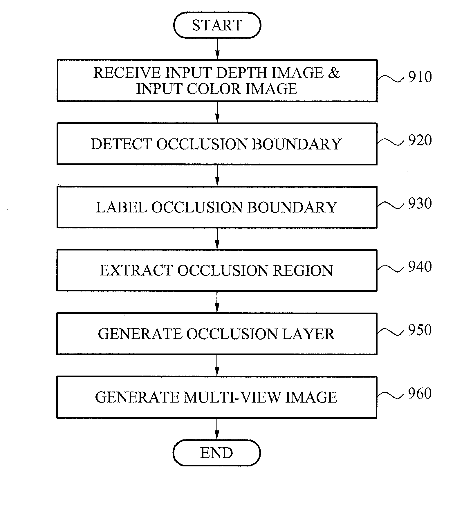
[0010]The image processing apparatus may further include an occlusion layer generator to restore a depth value of the occlusion region using a depth value of a region excluding the occlusion region in the input depth image.
[0012]The occlusion layer generator may restore the color value of the occlusion region using the at least a pixel value of the input color image matched with the input depth image, by employing at least one of an inpainting algorithm of a patch copy scheme and an inpainting algorithm of a partial differential equation (PDE) scheme. The edge detection algorithm may correspond to a Canny edge detection algorithm.

Problems solved by technology

When each view image corresponding to the multi-view image or the stereoscopic image is photographed at a single viewpoint instead of being directly photographed and then, another view image is generated through an image processing process, detecting of an occlusion region between objects and restoring color information of the occlusion region may become difficult.

Method used


Image

  • Image processing apparatus and method of generating a multi-view image
  • Image processing apparatus and method of generating a multi-view image
  • Image processing apparatus and method of generating a multi-view image

Examples


Embodiment Construction

[0031]Reference will now be made to embodiments, examples of which are illustrated in the accompanying drawings, wherein like reference numerals refer to like elements throughout. Embodiments are described below to explain the present disclosure by referring to the figures.

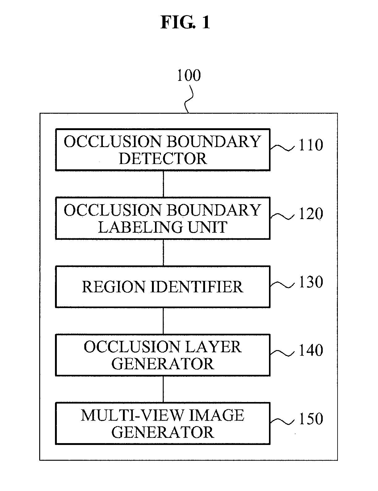
[0032]FIG. 1 illustrates an image processing apparatus 100 according to example embodiments.

[0033]An occlusion boundary detector 110 may detect an occlusion boundary within an input depth image by applying an edge detection algorithm to the input depth image.

[0034]The occlusion boundary detector 110 may employ a variety of schemes for detecting a continuous edge, for example, a Canny edge detection algorithm and the like. However, this is only an example.

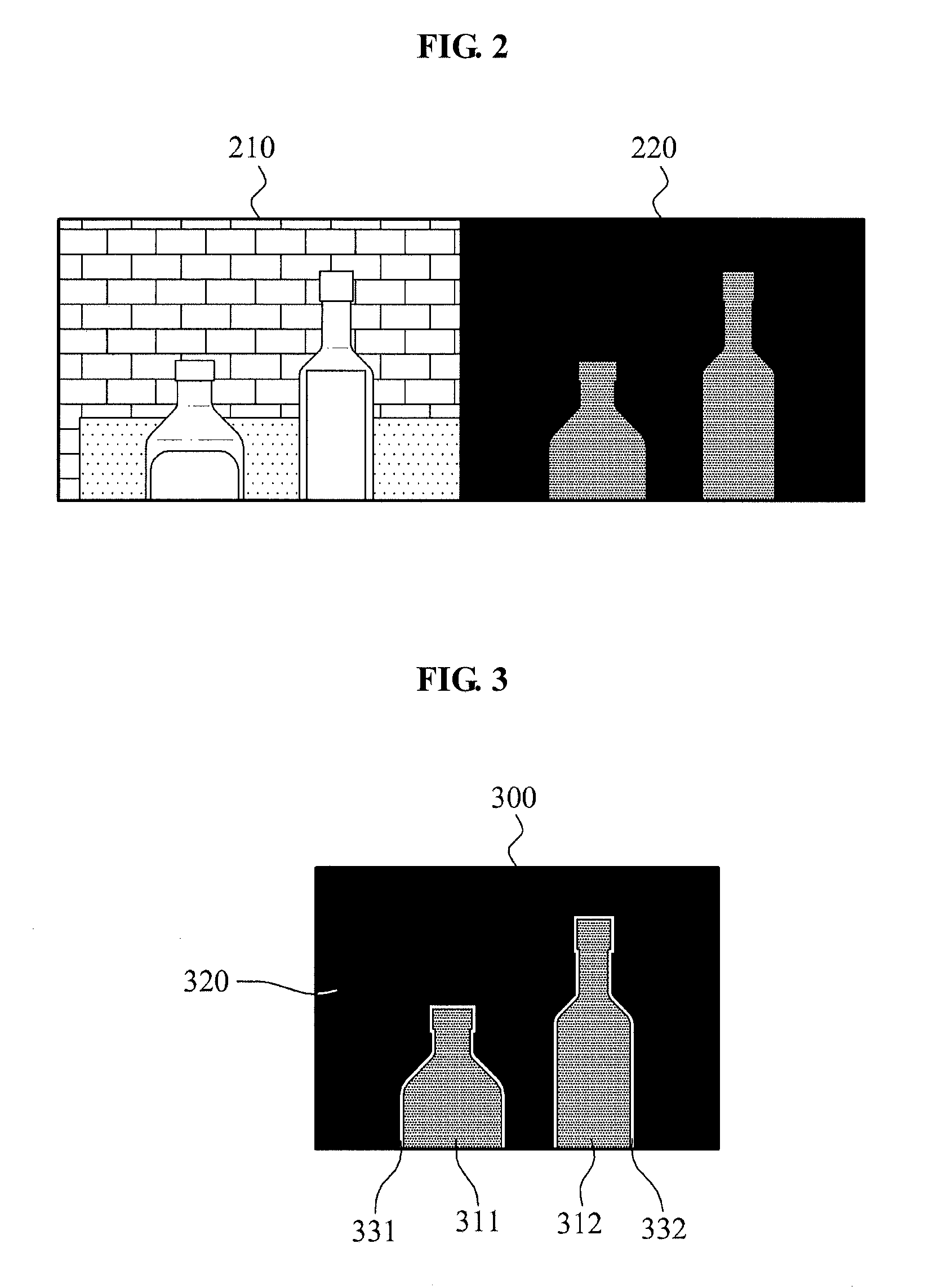
[0035]The occlusion boundary corresponds to a portion for separating a region determined as an occlusion region and a remaining region, and may be a band having a predetermined width, instead of a unit pixel line. For example, a portion may be classified as the oc...


PUM


Abstract

An image processing apparatus may detect an occlusion boundary between objects within an input depth image by applying an edge detection algorithm to the input depth image. The image processing apparatus may classify the occlusion boundary into a foreground region boundary and a background region boundary using a depth gradient vector direction of the occlusion boundary, and may extract an occlusion region of the input depth image using the foreground region boundary.

Description

CROSS-REFERENCE TO RELATED APPLICATIONS[0001]This application claims the priority benefit of Korean Patent Application No. 10-2010-0110994, filed on Nov. 9, 2010, in the Korean Intellectual Property Office, the disclosure of which is incorporated herein by reference.BACKGROUND[0002]1. Field[0003]Example embodiments relate to an apparatus and method of generating a multi-view image to provide a three-dimensional (3D) image, and more particularly, to an image processing apparatus and method that may detect an occlusion region according to a difference between viewpoints, and generate a multi-view image using the detected occlusion region.[0004]The example embodiments are related to the National Project Research supported by the Ministry of Knowledge Economy [Project NO.: 10037931] entitled The development of active sensor-based HD (High Definition)-level 3D (three-dimensional) depth camera.[0005]2. Description of the Related Art[0006]Currently, interest in three-dimensional (3D) image...

Claims


Application Information

Patent Timeline
IPC IPC(8): G06K9/00G06V10/46
CPCG06K9/48G06K9/00201G06V20/64G06V10/46
Inventor LIM, HWA SUPLEE, SEUNG KYUKIM, YONG SUN
Owner SAMSUNG ELECTRONICS CO LTD
Learn More