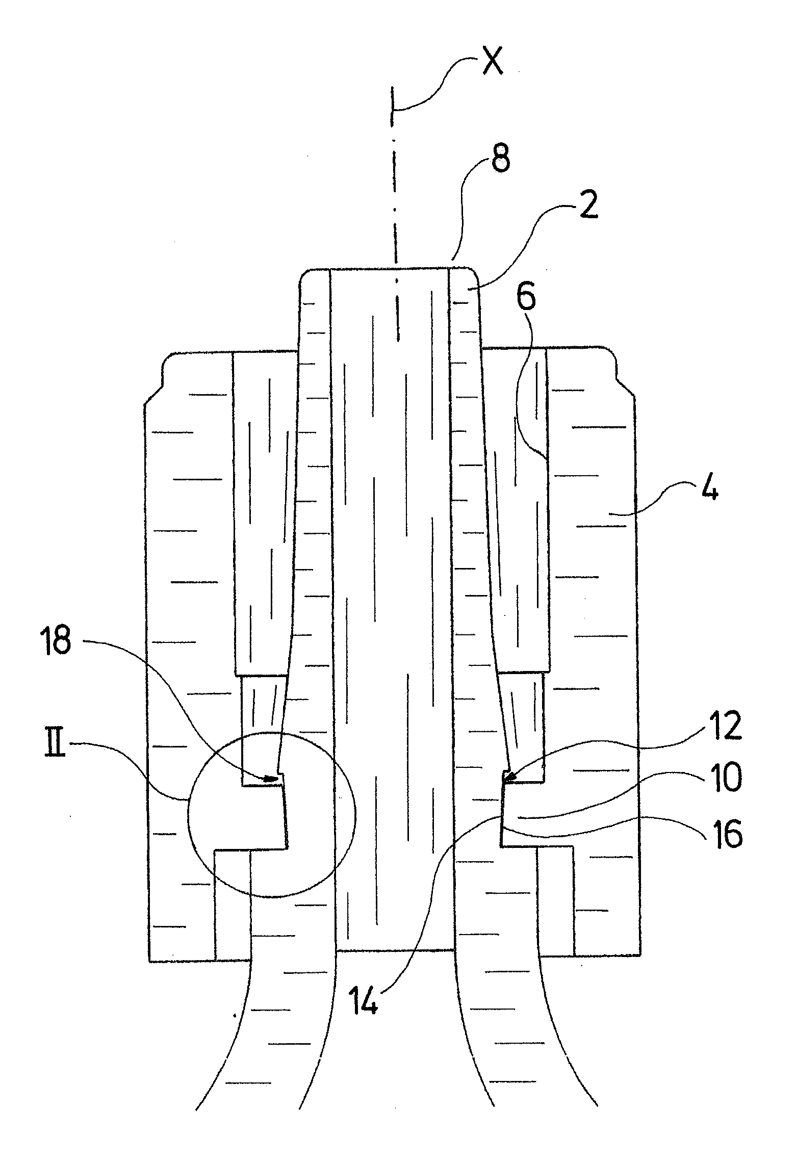
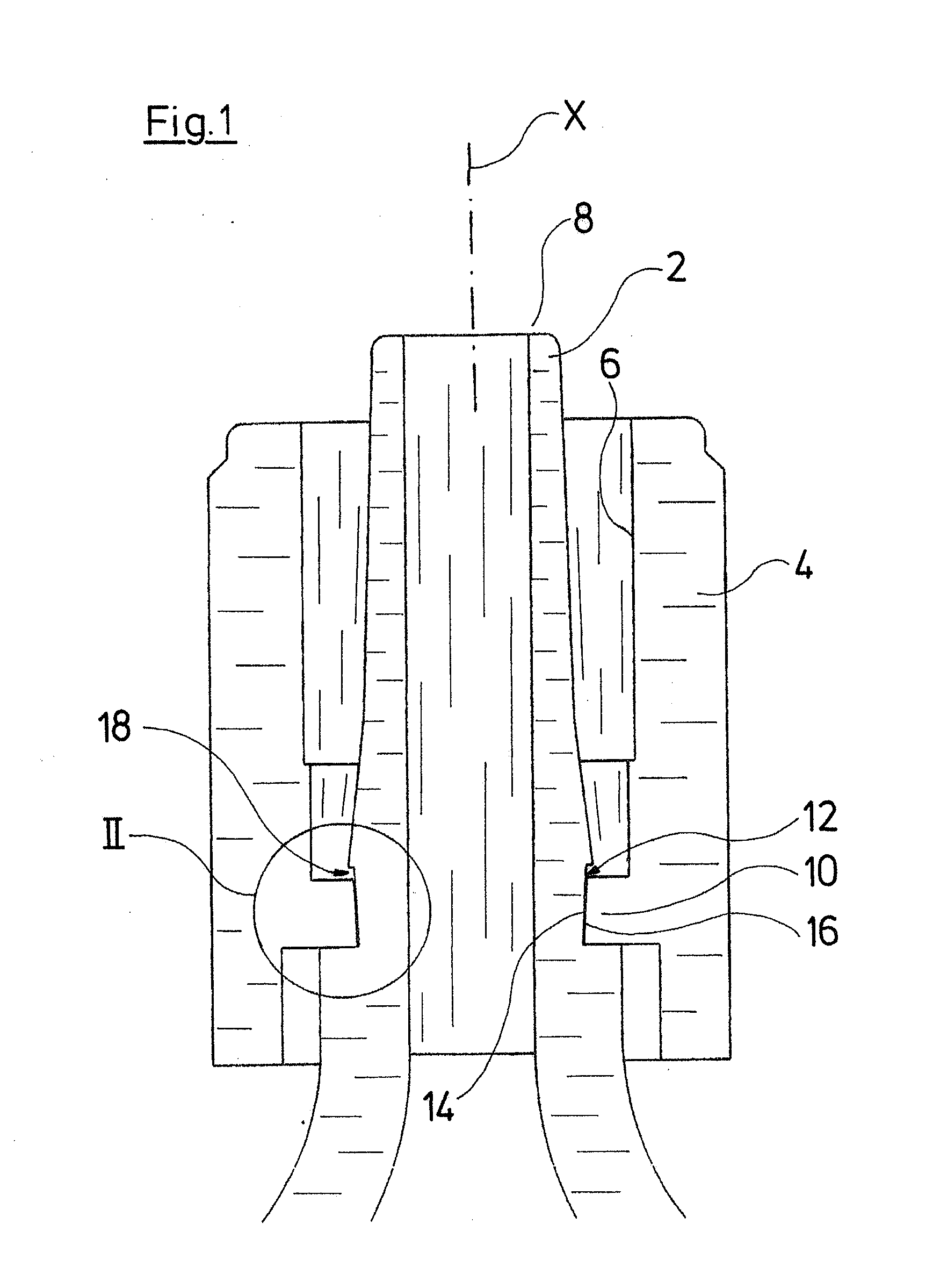
[0007]According to one embodiment of the invention, additional clamping elements are provided between the threaded sleeve and the foot of the Luer cone, and these clamping elements form a rotation lock when a female counter-piece is put onto the Luer cone or is screwed into the threaded sleeve. By way of these clamping elements, the threaded sleeve is then prevented from being able to rotate in an unintended manner, in particular on its own, for example by way of external shakings, whereby such a rotation would lead to a loosening of the connection between the Luer lock connection and the female counter-piece. The clamping elements are designed in a manner such that when a female counter-piece is put onto the Luer cone, they achieve a clamping between the threaded sleeve and the foot of the Luer cone by way of rotating the threaded sleeve or rotating the female counter-piece in the threaded sleeve. An additional securing or locking of the connection is achieved by way of this clamping. With conventional Luer lock connections, a locking between the conical outer surface of the Luer cone and the female counter-piece is achieved due to friction. Additionally, an axial locking is secured by way of the thread of the threaded sleeve. With conventional Luer lock connections, the threaded sleeve is however held in the thread merely by way of the friction. According to one embodiment of the invention, by way of the clamping elements, an additional friction-fit and / or positive-fit connection or clamping is now created directly between the threaded sleeve and its mounting at the foot of the Luer cone. The clamping elements, preferably directly on the threaded sleeve and / or on the foot of the Luer cone, are designed such that for additional securing, a positive-fit and non-positive fit engagement is effected between the threaded sleeve and the foot of the Luer cone, for rotational locking i.e. the clamping elements form engagement elements acting with a positive fit and non-positive fit. By way of this additional locking, one may create a secure retention, in particular also if
moisture or
lubricant should get onto the thread or the Luer cone. Since the clamping means according to the invention moreover are arranged in the
foot region of the Luer cone, i.e. at the end which is away from the free end of the Luer cone, one may prevent
humidity which exits from the Luer lock connection, for example with pre-filled cartridges, from getting in the region of the clamping means.
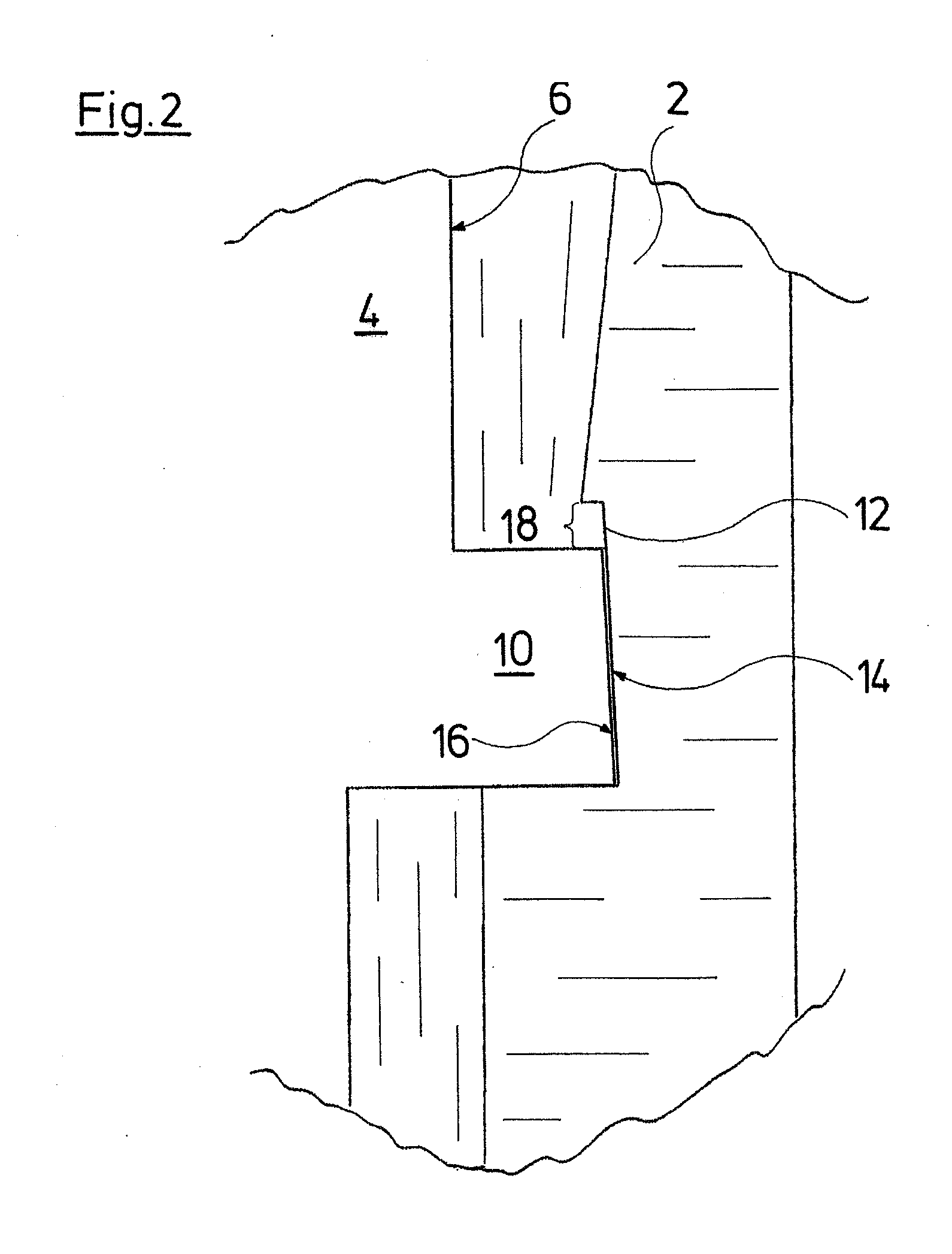
[0009]Further preferably, the threaded sleeve is held at the foot of the Luer cone with play which is dimensioned such that it is eliminated by way of the engagement of the female counter-piece with the Luer cone and the threaded sleeve, by which the contact surface and the counter-contact surface engage with one another. It may thereby be the case of an axial and / or radial play with respect to the longitudinal axis of the Luer cone. This play ensures the free rotatablity of the threaded sleeve as long as the female counter-piece is not put onto the Luer cone. Only then, by way of screwing the threaded sleeve onto the thread of the female counter-piece and / or screwing of the female counter-piece into the threaded sleeve, is the play eliminated either in the axial and / or radial direction, by way of the movement of the threaded sleeve relative to the foot of the Luer cone, so that the contact surfaces and the counter-contact surfaces come into engagement with one another.
[0012]According to a further preferred embodiment, the contact surface and / or the counter-contact surface are designed in an annular, in particular circularly annular manner. Thereby, the counter-contact surface may annularly encompass the contact surface. The contact surface and / or counter-contact surface may thereby be parts of the guiding of the threaded sleeve on the foot of the Luer cone. This means that the contact surface may be part of a groove on the foot of the Luer cone, for example the groove base or one of the groove walls. The counter-contact surface may thereby be a corresponding annular inner surface or one of the axial end-sides of a radially inwardly directed projection of the threaded sleeve which engages into the previously described groove. By way of the annular design of the contact surface and / or of the counter-contact surface, one may succeed in a clamping being achieved at any angular position between the Luer cone and the threaded sleeve. This is particularly advantageous, since usually the female counter-piece may be put onto the Luer cone also at any angular position with respect to the longitudinal axis of the Luer cone.
[0014]For this, the counter-contact surface is preferably designed in a manner which corresponds conically to the contact surface, i.e. the counter-contact surface is bevelled at the same angle with respect to the longitudinal axis of the Luer cone as the contact surface. The angle lies in a range of 6° which is similar to the angle of the Luer cone. The contact surface and counter-contact surface may contact in a large-surfaced manner by way of the corresponding conical design, so that a large friction between both surfaces and thus preferably a self-locking may be achieved.
[0015]Further preferably, the contact surface and the counter-contact surface are arranged concentrically to the longitudinal axis of the Luer cone. In the released condition, this permits the counter-contact surface to be moved in rotation about the contact surface or relative to the contact surface, so that the threaded sleeve may be rotated about the Luer cone.


