Gas meter

a gas meter and gas flow technology, applied in the field of gas meter, can solve the problems of affecting the measurement accuracy, the screen will become clogged to a certain extent with dirt collected, and the effect of reducing the accuracy of the measuremen

Inactive Publication Date: 2012-05-17
HYDROMETER GMBH
View PDF4 Cites 20 Cited by
  • Summary
  • Abstract
  • Description
  • Claims
  • Application Information

AI Technical Summary

Benefits of technology

[0019]Another embodiment of the insert envisages the use, as an insert, of a hollow body which is cylindrical in cross section, at least in a certain section, into which there opens a gas feed tube, which has the inflow opening and is coupled, e.g. directly, to the gas inlet, and from which hollow body the tube extends and thus merges into the measuring section. This cylindrical hollow body forms the inflow chamber. By virtue of its cylindrical shape, there is inevitably a rotation of the inflowing gas and, here too, the inflow opening is preferably arranged in a position laterally offset with respect to the overlapping tube. The insert can furthermore have a section which forms a second tube, in which the first tube is arranged. As already described above, there is the possibility of accommodating the tube in a second tube and thus implementing a double-walled construction, with the gas entering both partial volumes from the cylindrical hollow body. In this way, it is thus possible to separate a partial or bypass gas flow from the central main gas flow, with the central main gas flow preferably being used for further measurement.

Problems solved by technology

Since the gas has to be fed to a gas meter for purposes of recording consumption, the dirt particles and dust are also inevitably carried into the gas meter.
The contaminants contained in the gas can then settle on the sensor element or elements and can consequently have a disadvantageous effect on the measuring action or the measuring accuracy thereof.
Moreover, it cannot be excluded that the screens will become clogged to a certain extent with dirt that has been collected.
However, the division of the volume flow between the partial gas flow, also referred to as the bypass flow, and the main gas flow may change with respect to the volume flow, thereby reducing the useful measurement dynamics.

Method used


Image

  • Gas meter
  • Gas meter
  • Gas meter

Examples


Embodiment Construction

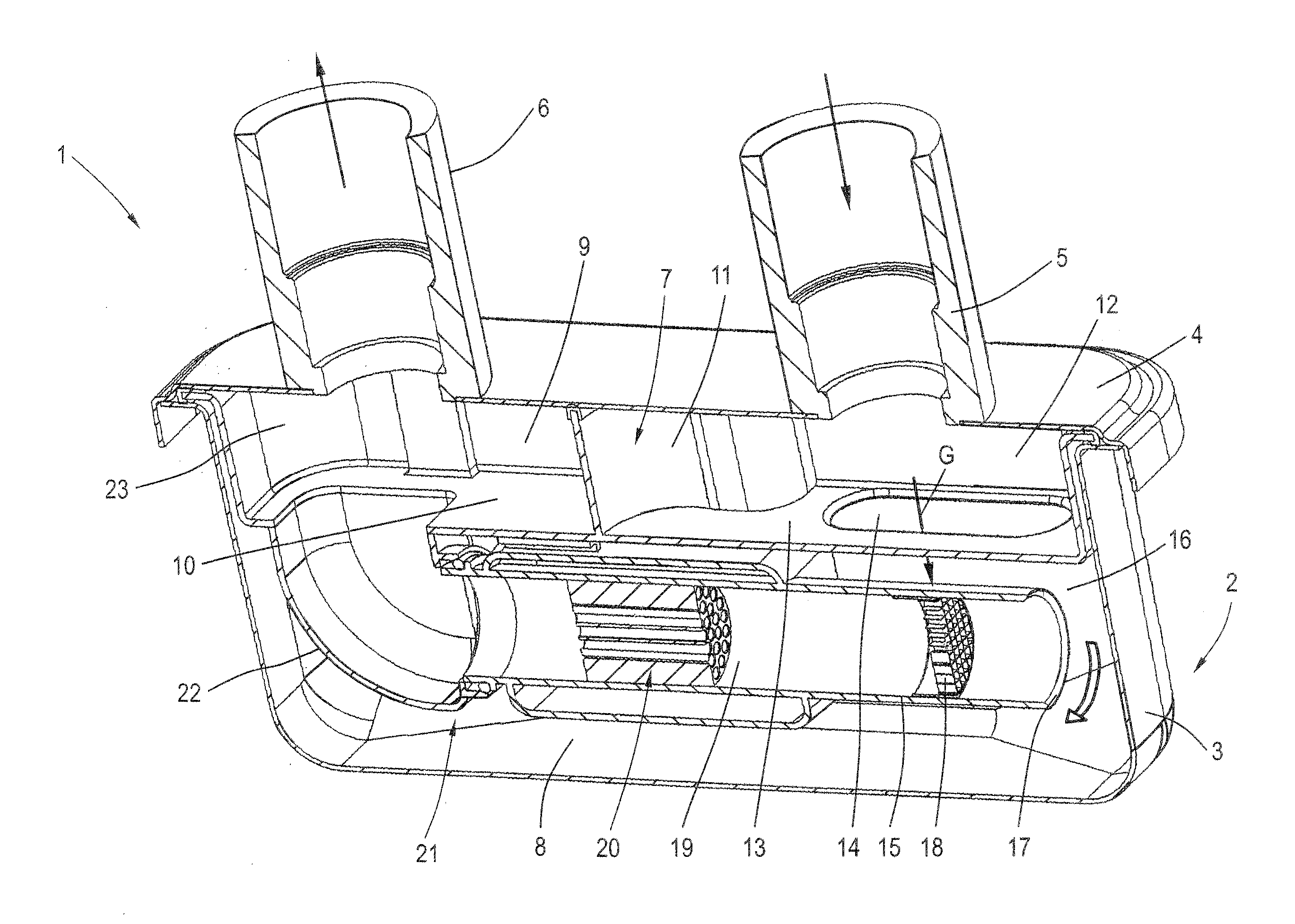
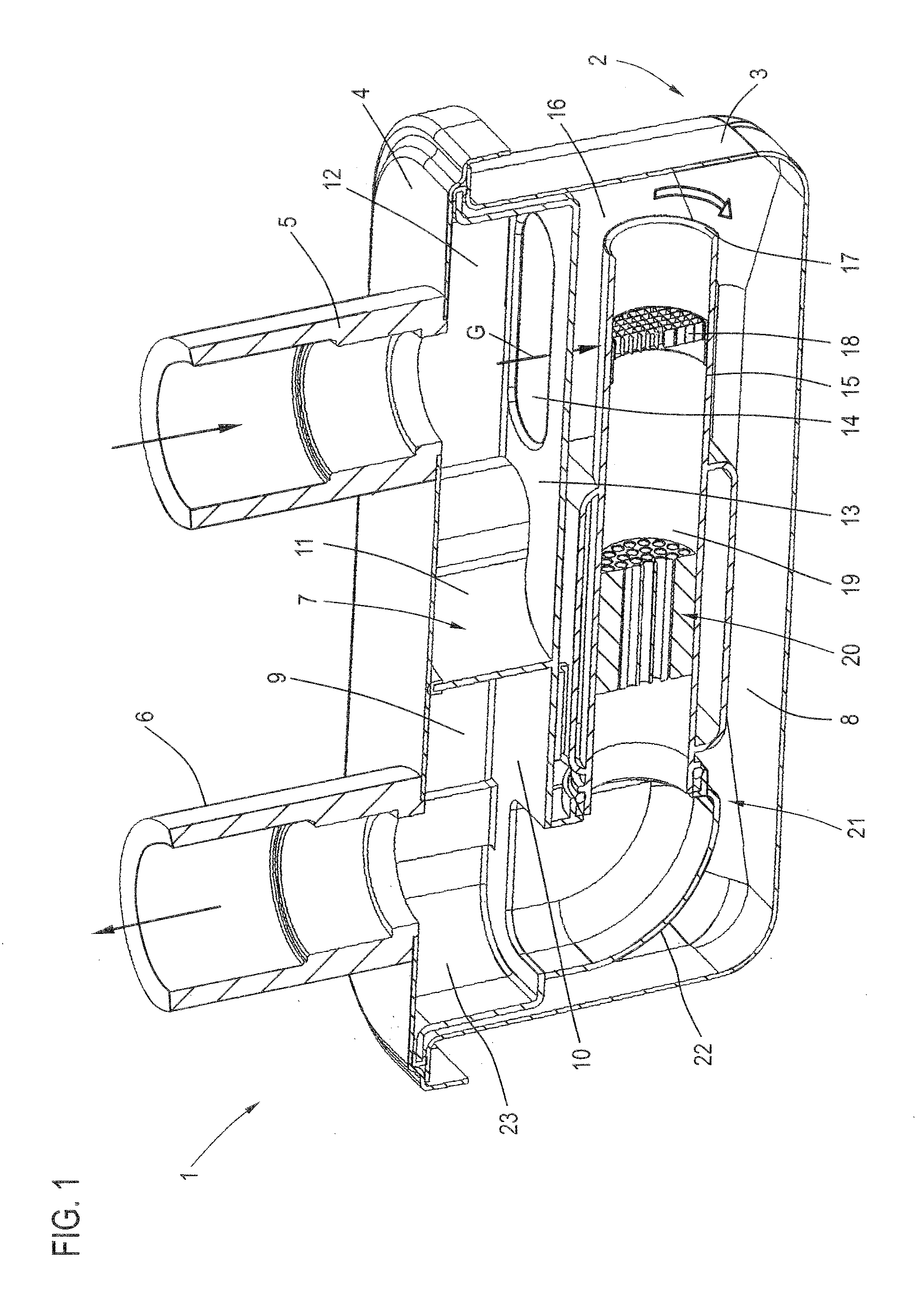
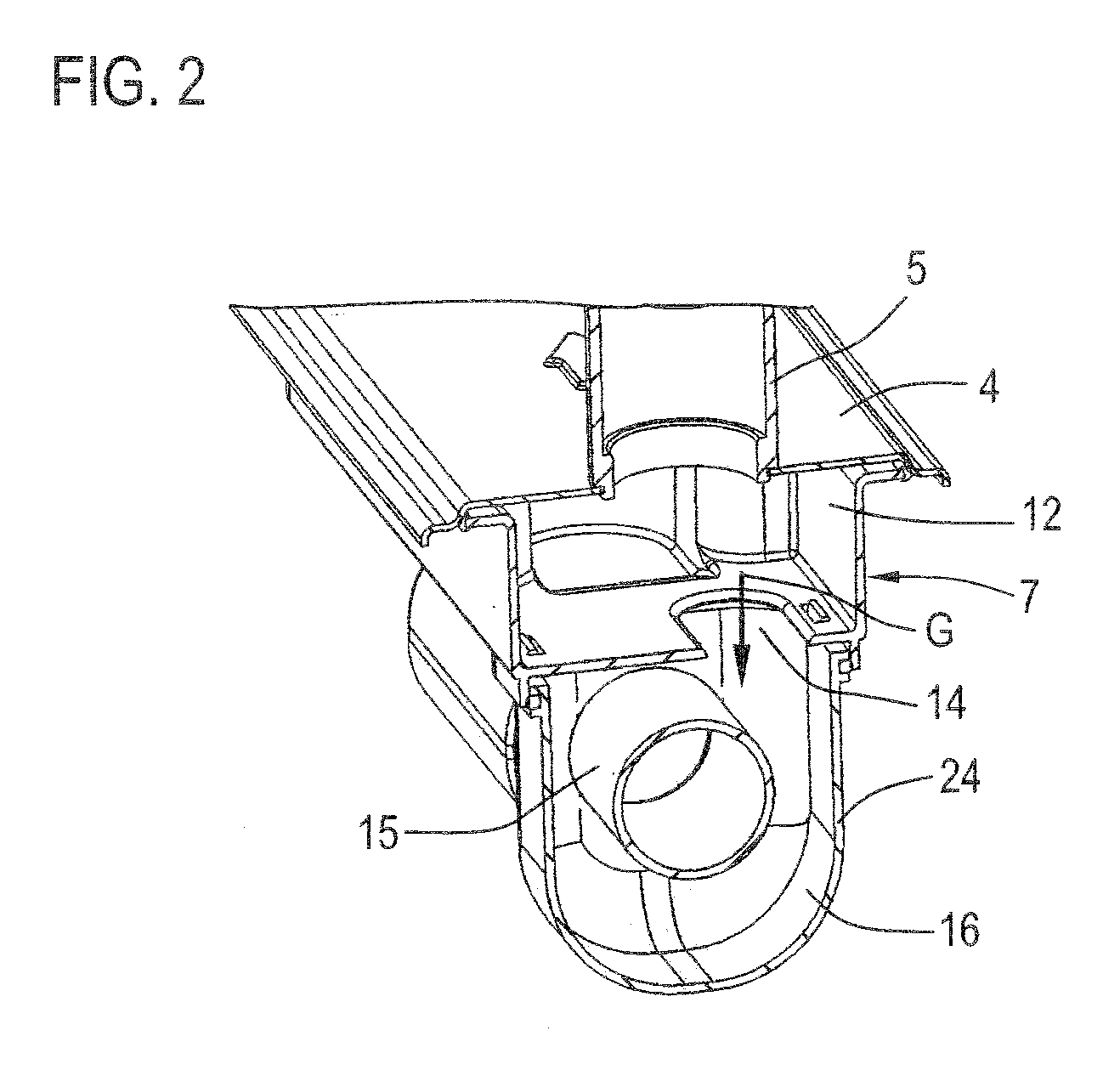
[0026]FIG. 1 shows a gas meter 1 according to the invention in a sectional representation. The gas meter 1 consists of a meter housing 2 comprising a lower, pot-shaped housing part 3 and a cover 4 which is placed thereon in a sealed manner and on which a gas inlet connection 5 and a gas outlet connection 6 are arranged as separate, spaced connections. Corresponding pipe conduits are connected to these.

[0027]In the housing 2 there is furthermore an insert 7, e.g. a plastic moulding, which is held in a sealed manner at the edges between the housing part 3 and the cover 4. Ultimately, the insert 7 divides the housing 2 into two regions, a lower housing region 8 and an upper housing region 9, which are separated from one another by a horizontally extending separation plane 10.

[0028]A dividing wall 11, which makes contact in a sealed manner with the cover 4, defines a pre-chamber 12, into which the gas inlet connection 5 opens. The dividing wall 11 is configured in such a way that, when ...


PUM


Abstract

A gas meter comprising a housing (2) with a gas inlet connection (5) and an inflow chamber (16) which is arranged downstream of the latter and into which gas flows via an inflow opening (14), arranged downstream of which inflow chamber (16) is a measuring section (19) arranged upstream of a gas outlet connection (6) and having a measuring device (20), in which the gas flow is measured, wherein projecting into the inflow chamber (16) there is a tube (15) which merges into the measuring section (19) or forms the latter and runs substantially perpendicularly to the gas flow direction through the inflow opening (14) and overlaps the inflow opening (14), at least in a certain section.

Description

CROSS-REFERENCE TO RELATED APPLICATIONS[0001]This application claims the benefit of U.S. Provisional Application No. 60 / 856,515 filed on November 3, 2006.BACKGROUND OF THE INVENTION[0002]The invention relates to a gas meter.DISCUSSION OF THE PRIOR ART[0003]Gas carried in natural gas lines contains a certain proportion of dirt particles and dust. Since the gas has to be fed to a gas meter for purposes of recording consumption, the dirt particles and dust are also inevitably carried into the gas meter. In the gas meter, the gas is guided past appropriate sensor elements that serve to measure the volume, e.g. a micro-thermal sensor. The contaminants contained in the gas can then settle on the sensor element or elements and can consequently have a disadvantageous effect on the measuring action or the measuring accuracy thereof.[0004]The practice known hitherto has been to integrate screens for collecting these contaminants into the natural gas lines or into the gas meter. This is an inv...

Claims


Application Information

Patent Timeline
Patent Type & Authority Applications(United States)
IPC IPC(8): F17D3/00
CPCG01F1/68G01F15/12G01F1/6842Y10T137/8158
Inventor SONNENBERG, HANS-MICHAELHEGENDOERFER, ANDREAS
Owner HYDROMETER GMBH
Why Eureka
Try Eureka