Device for fixating cables with pull relief

a technology of fixing device and cable, which is applied in the direction of cable junction, cable termination, electrical apparatus, etc., can solve the problems of contaminants and humidity not being able to penetrate along the cable and through the device, and achieve the effect of reducing the inner diameter of the sleeve component and high toleran

Inactive Publication Date: 2012-05-17
LUMBERG CONNECT
View PDF6 Cites 3 Cited by
  • Summary
  • Abstract
  • Description
  • Claims
  • Application Information

AI Technical Summary

Benefits of technology

[0008]It is an advantage of the invention that the insert reduces the inner diameter of the sleeve component in the portion of the crush lamellas and adapts the inner diameter to a particular cable diameter that is smaller than the inner diameter of the sleeve component. By threading on the cap nut the crush lamellas are not pressed against the insert component. Thus, the insert component which has a certain amount of elasticity is pressed against the outer circumferential surface of the cable and retains the cable in the device through friction locking.
[0009]It is provide that the insert reducing the inner circumference includes a seal sleeve or is formed by a deal sleeve. A sleeve of this type not only advantageously adapts the inner circumference of the sleeve component to the cable to be supported, but simultaneously seals the device towards the outside. Consequently dust, contaminants and humidity cannot penetrate along the cable and through the device into an eventually closed junction box.
[0010]It is furthermore provided that the insert that reduces the inner circumference in turn also includes a support sleeve provided with crush lamellas. The advantage of a device configured in that manner is the crush lamellas of the insert have a higher tolerance with respect to different cable diameters. Furthermore the crush lamellas of the insert provide a safe fixation of the cable in the device. Contrary to the preceding embodiments an insert of this type is configured to support cables with various diameters. Thus it is provided that the crush lamellas of the sleeve component impact the crush lamellas of the support sleeve of the insert directly or indirectly.
[0011]A particular embodiment is characterized in that the insert reducing the inner circumference is formed by the seal sleeve and the support sleeve, wherein the seal sleeve arranges the support sleeve between itself and the second axial portion of the sleeve component. This embodiment combines the advantages of the insert with the support sleeve and the insert with seal sleeve.
[0012]It is furthermore provided that the second axial portion of the sleeve component configures a receiver for the insert on its inner circumference, in particular when the receiver secures the insert at least against an axial movement in insertion direction of a cable into the sleeve component.
[0013]Eventually it is provided that the sleeve component forms a portion of a junction box for solar modules.

Problems solved by technology

Consequently dust, contaminants and humidity cannot penetrate along the cable and through the device into an eventually closed junction box.

Method used


Image

  • Device for fixating cables with pull relief
  • Device for fixating cables with pull relief
  • Device for fixating cables with pull relief

Examples


Embodiment Construction

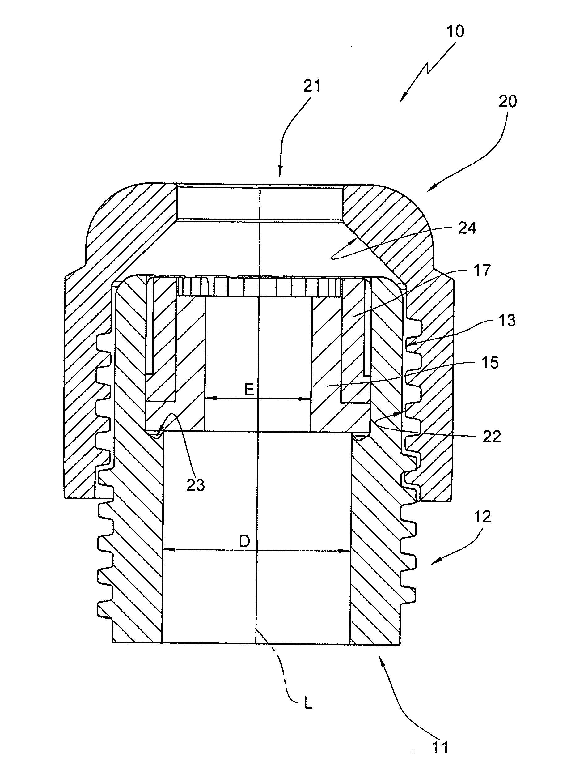
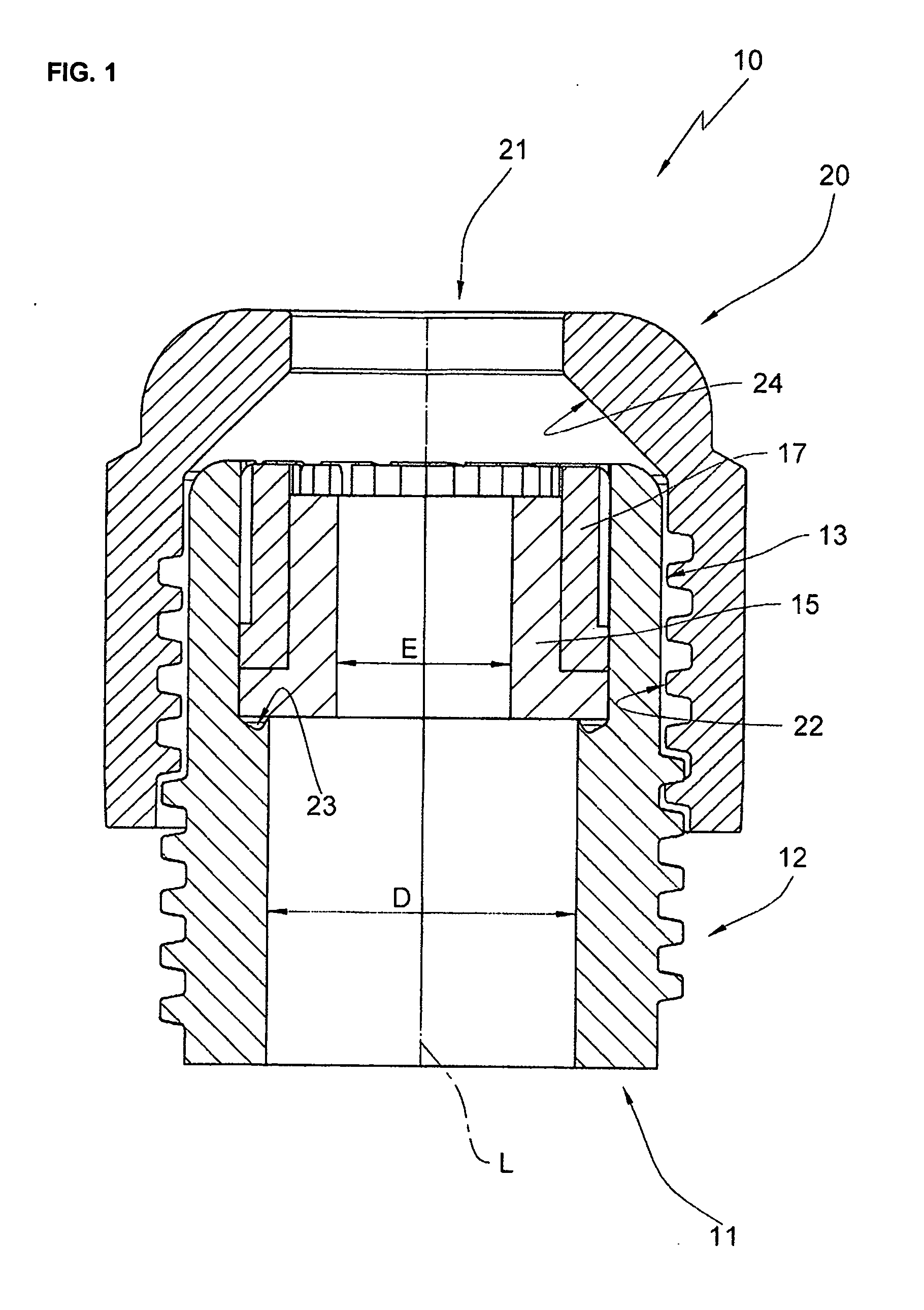
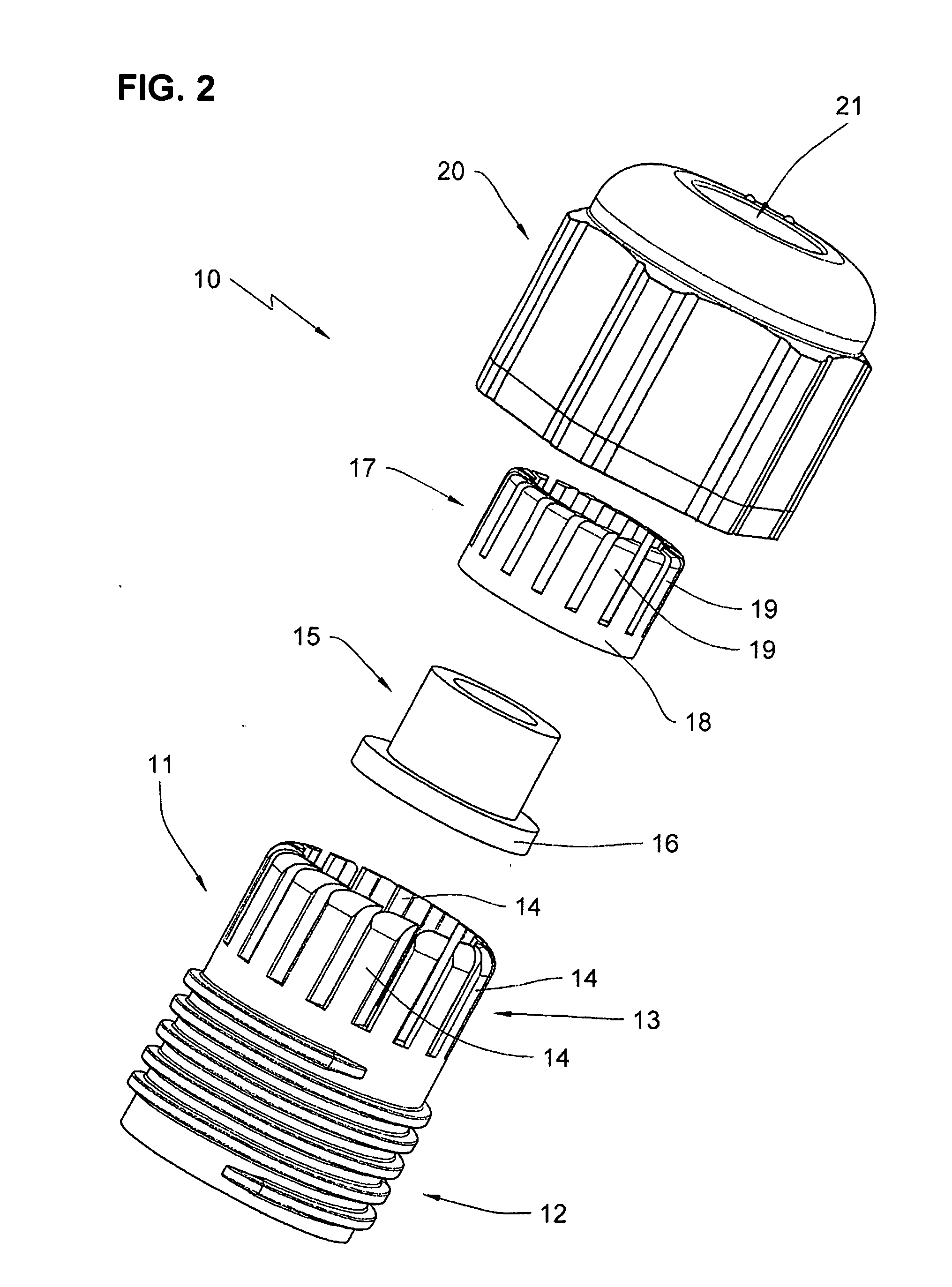
[0017]A device for fixating cables with pull relief is designated overall with the reference numeral 10. The device 10 includes a sleeve component which is designated overall with the reference numeral 11. The sleeve component 11 includes two axial portions or axial sections. The first axial section 12 is provided with an outer circumferential thread and can therefore be also designated as threaded section 12. The second axial section 13 is formed by the crush lamellas 14 and can therefore also be designated as lamella section 13. Typically the sleeve section 11 forms an integral one piece component with a junction box or an applied or integrally formed component of a junction box, in particular a junction box for solar modules.

[0018]The device 10 furthermore includes a seal sleeve 15 which is advantageously made from an elastic material. The inner diameter of the seal sleeve 15 is less than the inner diameter of the sleeve component 11. Furthermore the seal sleeve 15 is configured ...


PUM


Abstract

A device for fixating cables with pull relief, including a sleeve component including an outer thread in a first axial portion and a second axial portion that is formed by crush lamellas which are pressed against an outer circumferential surface of a cable that is being fixated. The crush lamellas are pressed against the outer circumferential surface of the cable by a cap nut that is threaded onto the outer thread and provided with a cable pass through opening. The sleeve component is provided with an insert on an inner circumference of its second axial portion that is formed by the crush lamellas, wherein the insert reduces the inner diameter of the sleeve component.

Description

RELATED APPLICATIONS[0001]This application claims priority from and incorporates by reference German patent application DE 10 2010 047 239.5-55 filed on Oct. 4, 2010.FIELD OF THE INVENTION[0002]The invention relates to a device for fixating cables with pull relief, including a sleeve component which includes an outer circumferential thread in a first axial portion and whose second axial portion is formed by crush lamellas which are pressed against an outer circumferential surface of the cable to be fixated through a cap nut that is being threaded onto the thread and that includes a cable pass through opening.BACKGROUND OF THE INVENTION[0003]These devices are often threaded sleeves arranged at junction boxes for electrical cables, wherein crush lamellas of the threaded sleeves are pressed against an outer surface of a cable through a cap nut, wherein the cable shall be inserted through the cap nut and the sleeve into the junction box. Thus, the cable is fixated at the junction box wi...

Claims


Application Information

Patent Timeline
Patent Type & Authority Applications(United States)
IPC IPC(8): H02G15/02
CPCH02G3/0675H02G3/0666H02G15/18H02G3/16
Inventor RICHTER, MICHAEL
Owner LUMBERG CONNECT
Why Eureka
Try Eureka