
Medical valve with a variable diameter seal

a variable diameter, valve technology, applied in the field of hemostatic valves and systems, can solve the problems of disk valves that are not designed to provide effective seals across a wide range of different sized medical devices, deformation, tear or dislocation, etc., and achieve the effect of less compression, improving the performance and reliability of the elastomeric seal

Active Publication Date: 2018-09-13
FREUDENBERG MEDICAL
View PDF1 Cites 0 Cited by
  • Summary
  • Abstract
  • Description
  • Claims
  • Application Information

AI Technical Summary

Benefits of technology

The patent is about a medical valve assembly used to insert a medical device into a patient's body vessel. The assembly includes a tube, plunger plate, and valve housing. An elastomeric seal is compressed between the plunger plate and the valve housing to establish a variable seal. A compression member is placed inside the valve housing and pushes the plunger plate to close the valve. The inner surface of the elastomeric seal has alternating planar and radiused portions, which improves performance and reliability of the seal.

Problems solved by technology

However, disk valves are subject to deformation with both time and use, and often can tear or become dislodged during insertion and / or withdrawal of the medical device.
Furthermore, disk valves are not designed to provide an effective seal across a wide range of differently sized medical devices.
Although the disk valve can be modified to accommodate these situations, such as with increased tensile and / or elongation properties, this modification leads to increased resistance, and thus require the use of excessive force, when the medical device is inserted and withdrawn through the disk valve.
Additionally, even when the elastomeric sleeve is held in the closed position, gaps or channels extend therethrough as a result of the twisting or infolding required to effectuate a closure.
Further, the continuous twisting and constricting of the elastomeric sleeve leads to wear of the sleeve, such as through tearing.
The drawbacks associated with the existing medical valves are further exemplified when one considers that a single medical valve often is used to insert multiple medical devices during a single procedure.
Additionally, the hemostatic valve device must be able to quickly adjust to use of each of these different medical devices, otherwise significant fluid loss can occur through the medical valve.

Method used


Image

  • Medical valve with a variable diameter seal
  • Medical valve with a variable diameter seal
  • Medical valve with a variable diameter seal

Examples


first embodiment

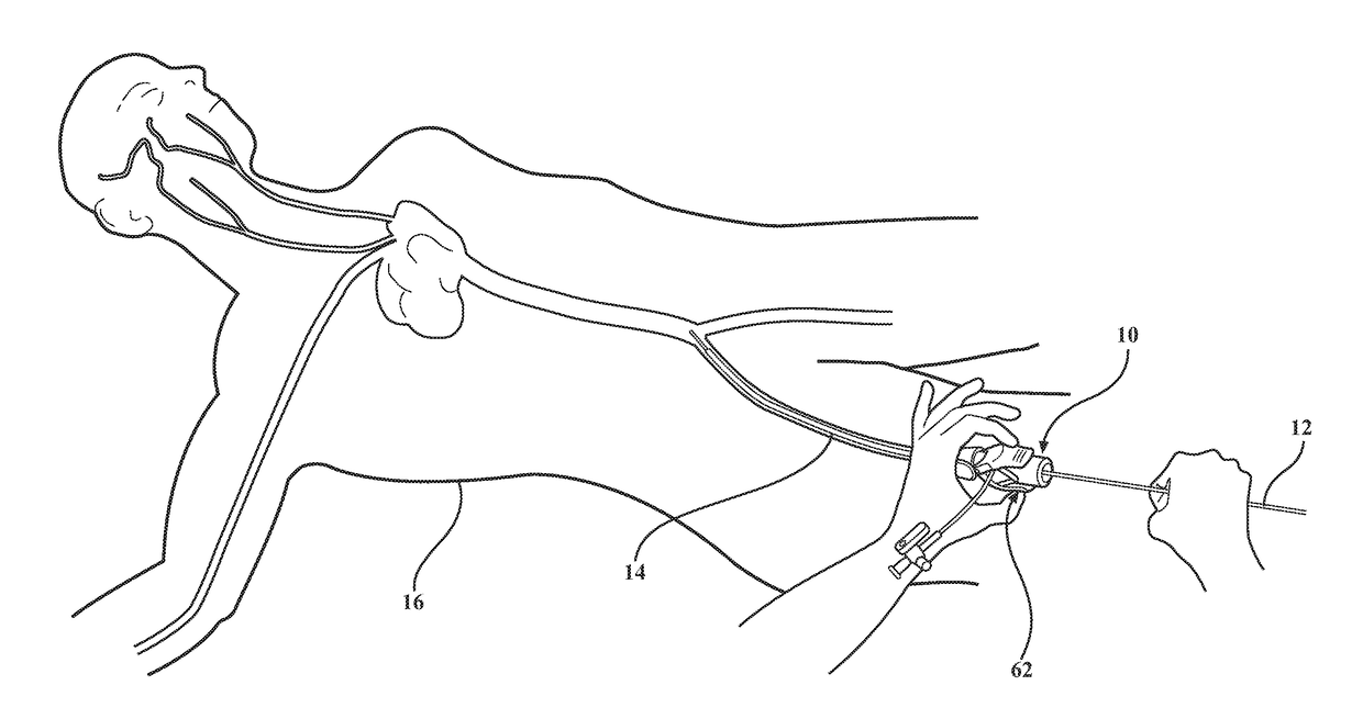
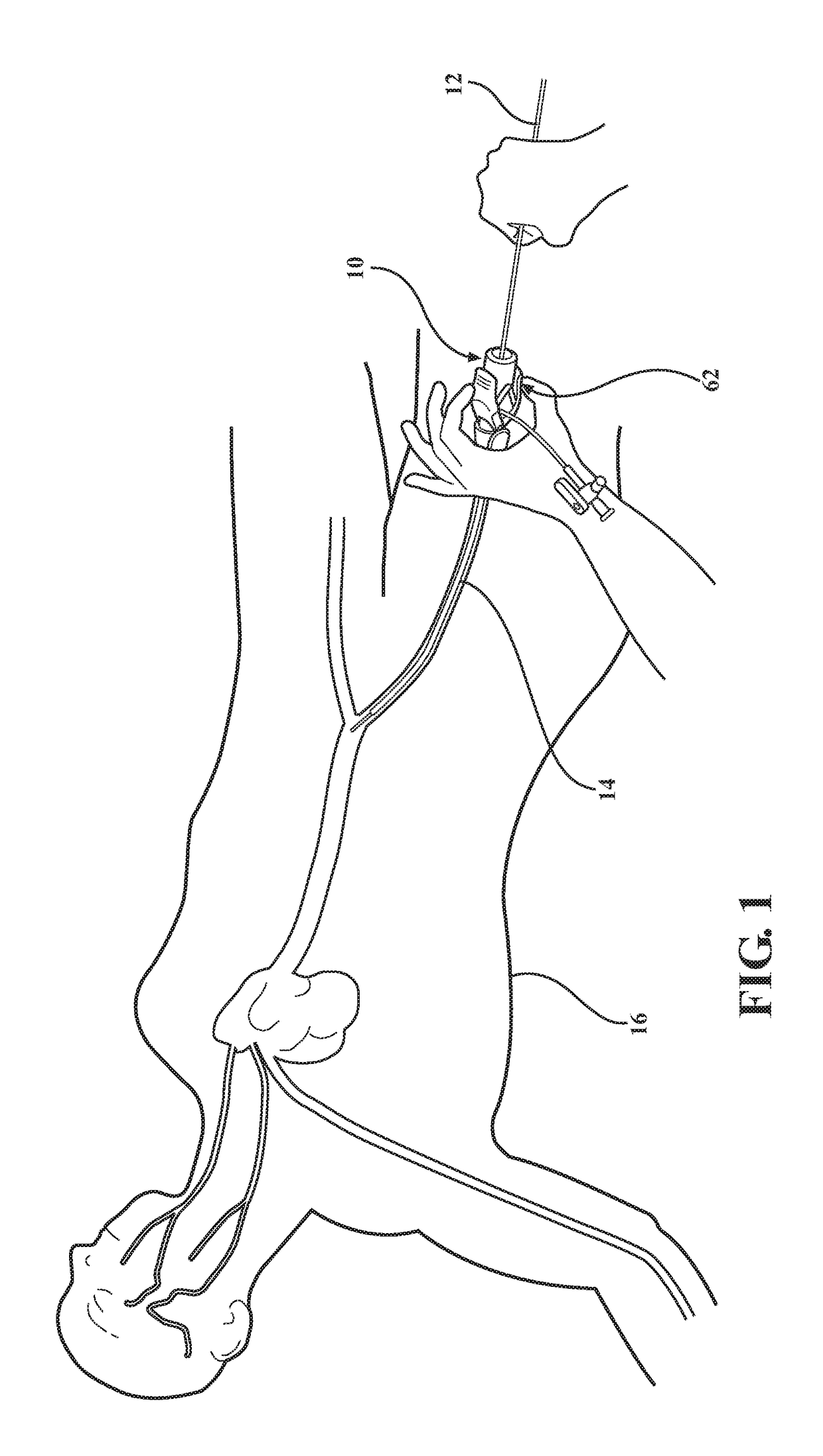
[0033]As best shown in FIGS. 4A, 4B, 11A and 11B, in medical valve assembly 10, the compression member 48, 54 comprises a coil spring 48 radially disposed between the valve housing 32 and the tube 20 and compressed between the first valve housing end 34 and the plunger plate 28. However, any other suitable compression member could be utilized without departing from the scope of the subject disclosure. In a preferred embodiment, a disk 50 is slidably disposed around the tube 20 and interconnected to the first valve housing end 34 to establish a shoulder 52 extending radially inward from the valve housing 32 and which is disposed in engagement with the coil spring 48. The coil spring 48 acts to bias the valve housing 32 towards the first tube end 22 for compressing the elastomeric seal 44 between the flange 38 and the plunger plate 28 and normally position the elastomeric seal 44 in its closed position. The valve housing 32 is then axially movable from the closed position and relative...

second embodiment

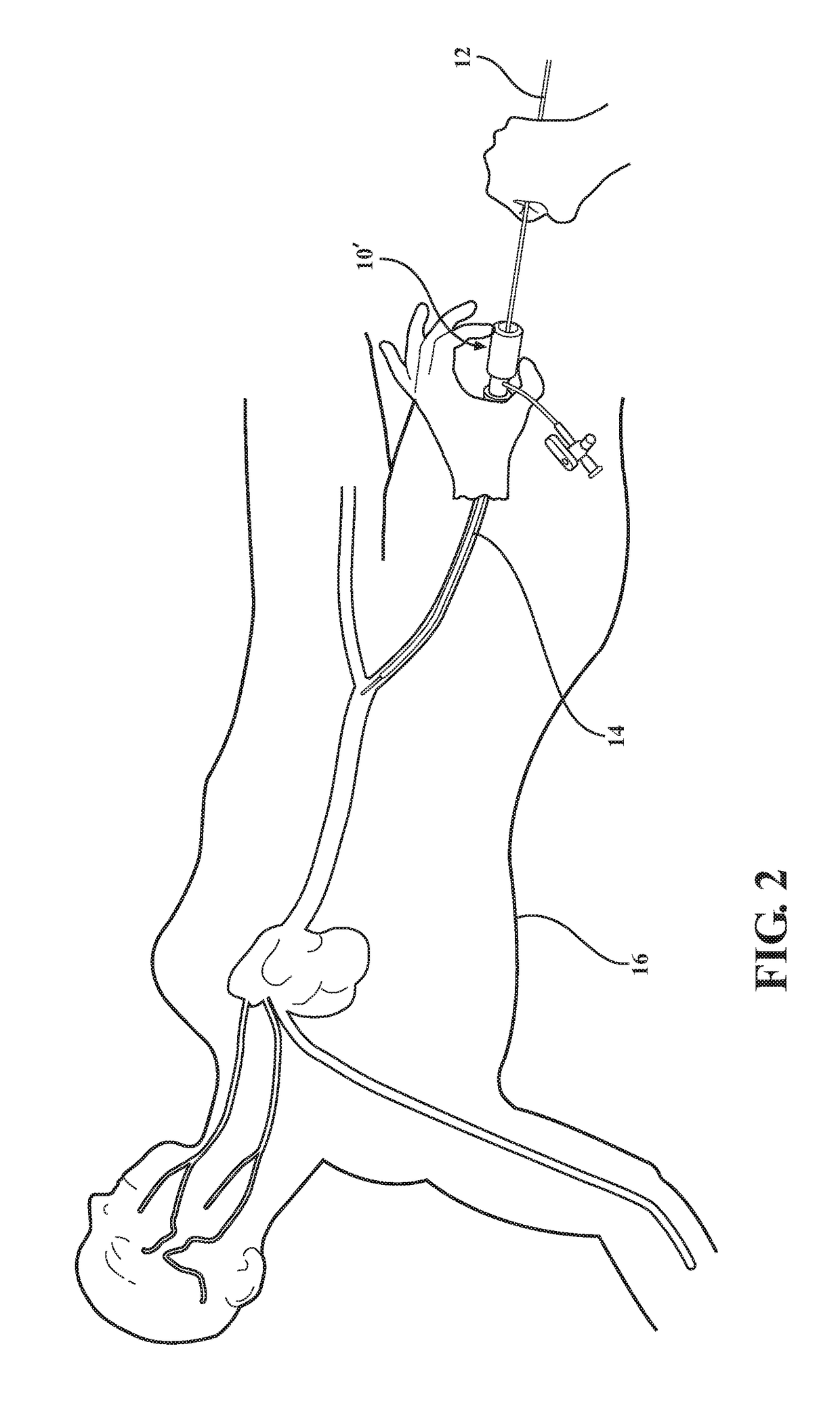
[0034]As best shown in FIGS. 8 and 9, in the medical valve assembly 10′, the compression member 48, 54 also comprises a coil spring 48 radially disposed between the valve housing 32 and the tube 20 and compressed between the first valve housing end 34 and the plunger plate 28. However, any other suitable compression member could be utilized without departing from the scope of the subject disclosure. The valve housing 32 defines a shoulder 52 extending radially inward from the first valve housing end 34 and slidably disposed around the tube 20. The shoulder 52 is disposed in engagement with the coil spring 48, and the coil spring 48 acts to bias the valve housing 36 towards the first tube end 22. In a preferred embodiment, the compression member 48, 54 additionally includes a leaf spring cage 54 disposed in surrounding relationship with the elastomeric seal 44. However, any other suitable compression member could be utilized without departing from the scope of the subject disclosure....


PUM


Abstract

A medical valve assembly includes a tube extending between a first and second tube end along an axis, and a plunger plate extends radially from the second tube end. A valve housing surrounds the tube and includes a radially inwardly extending flange. A compression member is biased against the plunger plate and compresses an elastomeric seal from a non-compressed condition to a compressed condition to establish a sealed condition of the medical valve assembly. An inner surface of the elastomeric seal in the non-compressed condition has a plurality of planar portions and a plurality of radiused portions, with adjacent planar portions interconnected with one of the radiused portions to improve a closure of the elastomeric seal during compression. The inner surface preferably includes three planar portions and three radiused portions to define a generally triangular-shaped inner surface as viewed in cross section in the non-compressed condition.

Description

CROSS-REFERENCE TO RELATED APPLICATIONS[0001]This application is a continuation-in-part of U.S. patent application Ser. No. 15 / 483,089 filed on Apr. 10, 2017, which is a continuation of U.S. patent application Ser. No. 14 / 326,593 filed on Jul. 9, 2014, now U.S. Pat. No. 9,616,213, the entire disclosures of which are incorporated herein by reference.BACKGROUND OF THE INVENTION1. Field of the Invention[0002]The present disclosure relates generally to medical devices and procedures. In particular, the present disclosure relates to hemostatic valves and systems, and methods of using the same.2. Description of the Prior Art[0003]This section provides background information related to the present disclosure which is not necessarily prior art.[0004]Numerous procedures have been developed that involve the percutaneous insertion of a medical device into a body vessel of a patient, with the medical device being introduced into the vessel by a variety of known techniques. Each of these procedu...

Claims


Application Information

Patent Timeline
Patent Type & Authority Applications(United States)
IPC IPC(8): A61M39/06A61B1/018A61B1/00
CPCA61M39/0613A61B1/018A61B1/00137A61M2039/0673A61M2039/0633A61M2039/062A61M39/10
Inventor FURNISH, GREGAPPLING, ANTHONYMORRIS, BENZEIS, TIMOTHY S.
Owner FREUDENBERG MEDICAL
Learn More