Liquid delivery pump

a liquid delivery pump and plunger seal technology, which is applied in the direction of positive displacement liquid engines, piston pumps, liquid fuel engines, etc., can solve the problems of acceleration in the etc., and achieve the suppression of the reduction of the liquid delivery accuracy, the effect of easy supply and suppressing the wear and deterioration of the plunger seal

Active Publication Date: 2016-12-22
SHIMADZU CORP
View PDF10 Cites 0 Cited by
  • Summary
  • Abstract
  • Description
  • Claims
  • Application Information

AI Technical Summary

Benefits of technology

[0013]According to the embodiment of the liquid delivery pump of the present invention, the cleaning space containing cleaning liquid is provided on the tip end side of the pump body, the plunger passage hole on the tip end surface of the pump body has an inner diameter of a size allowing the cleaning liquid in the cleaning space to flow out to the pump head side, and the backup ring has a through hole, for allowing penetration of the plunger, formed in a manner not allowing the plunger seal to enter a gap to the outer circumferential surface of the plunger and includes a liquid passage element for allowing the cleaning liquid in the cleaning space to reach the plunger seal through the through hole, and thus, the cleaning liquid in the cleaning space may be supplied to the plunger seal, and the slideability between the plunger and the plunger seal may be secured by using the cleaning liquid in the cleaning space. Wear and deterioration of the plunger seal may thereby be suppressed, and reduction in the liquid delivery accuracy may be suppressed.
[0014]Additionally, if the inner diameter of the plunger passage hole on the tip end surface of the pump body is reduced to prevent the plunger seal from entering the gap of the plunger passage hole, the backup ring becomes unnecessary, and the cleaning space can be brought closer to the plunger seal by the thickness of the backup ring and the cleaning liquid in the cleaning space can be easily supplied to the plunger seal. However, as described above, if the inner diameter of the plunger passage hole on the tip end surface of the pump body is reduced, the outer circumferential surface of the plunger may come into contact with the inner circumferential surface of the hole due to, for example, the influence of the assembly tolerance of the pump body and pump head. Such a problem is solved by mounting, on the pump head side, the backup ring for preventing deformation of the plunger seal. However, if the backup ring is inserted on the back surface side of the plunger seal, passing of the cleaning liquid may be interfered with by the smallness of the inner diameter of the backup ring, and it may become difficult to supply the cleaning liquid to the plunger seal.
[0015]The embodiment described above of the present invention aims to suppress wear and deterioration of the plunger by allowing cleaning liquid to be easily supplied to the plunger seal, with the backup ring inserted on the back surface side of the plunger seal.

Problems solved by technology

If the slideability between the outer circumferential surface of the plunger and the inner circumferential surface of the plunger seal is reduced, the plunger seal is worn out, and there are problems of liquid leakage due to seal failure on the outer circumferential surface of the plunger, and acceleration in the deterioration of the plunger seal due to frictional heat.

Method used


Image

  • Liquid delivery pump
  • Liquid delivery pump
  • Liquid delivery pump

Examples


Embodiment Construction

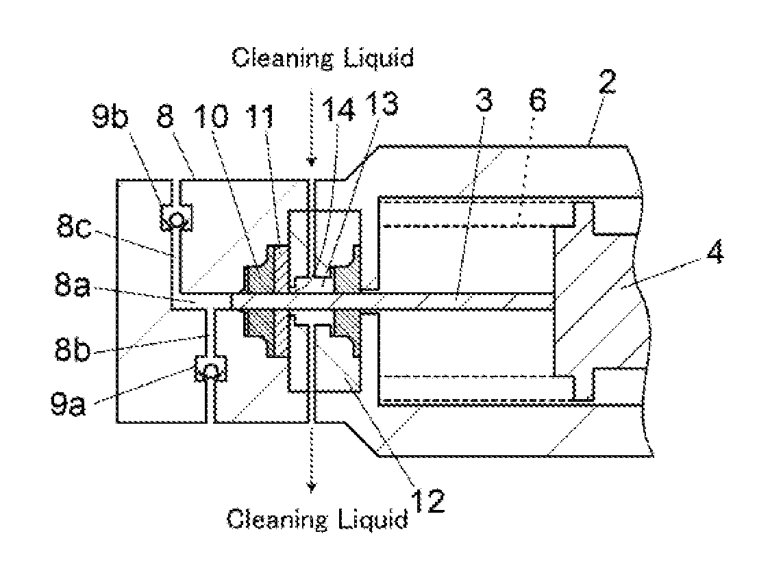
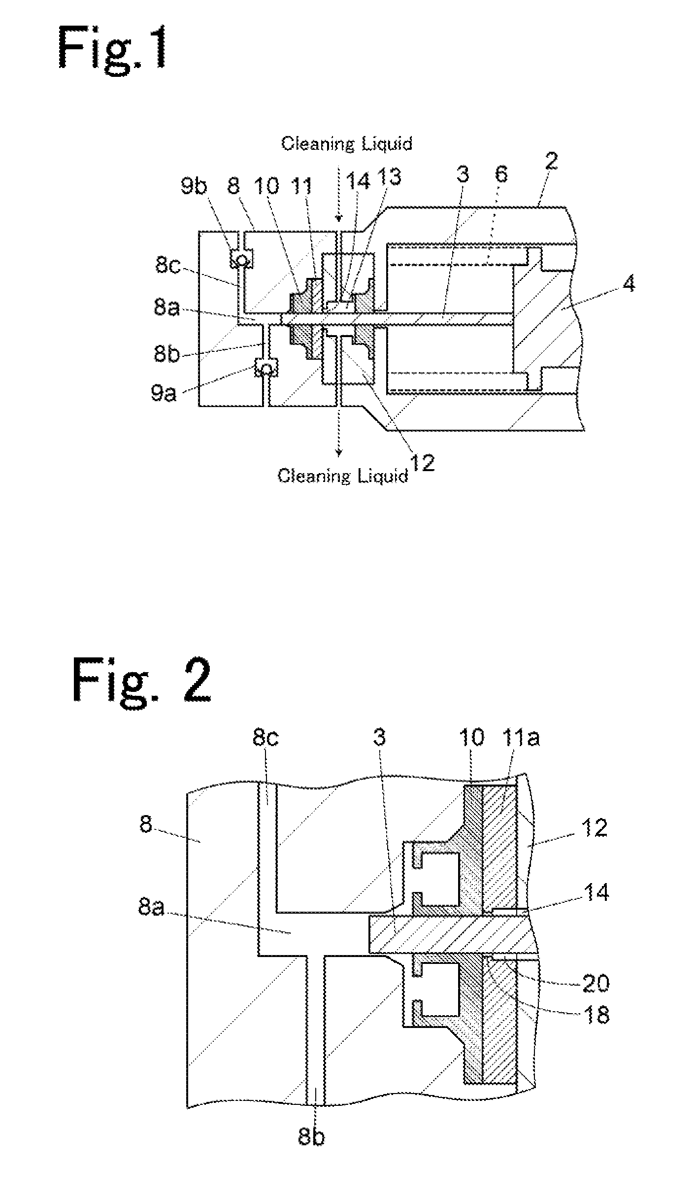
[0022]As a preferred embodiment of a liquid delivery pump according to the present invention, one may be cited that is provided with a recessed section about the same size or larger than a plunger passage hole and serving as a liquid passage element at a center portion of a surface, of a backup ring, on a pump body side, the recessed section being provided with a through hole at its center. According to such a structure, cleaning liquid flowing out of a cleaning space is stored at a position close to a plunger seal, and the cleaning liquid may be easily supplied to the plunger seal.

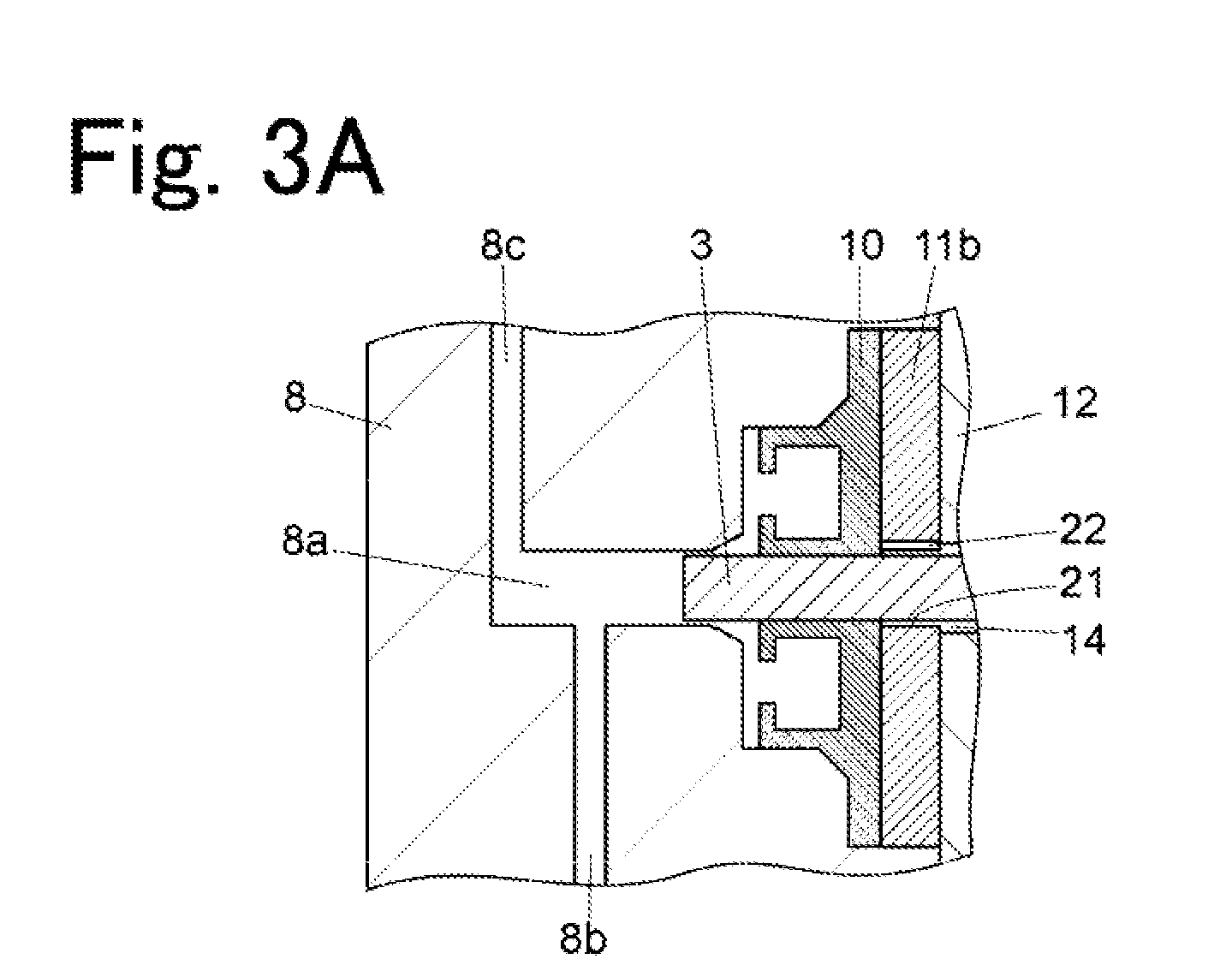
[0023]Also, a groove where the cleaning liquid from the cleaning space is to pass through may be provided, as a liquid passage element, on the inner circumferential surface of the through hole of the backup ring. According to such a structure, it is possible to supply the cleaning liquid to the plunger seal while preventing the plunger seal from entering the through hole of the backup ring.

[0024]Further, ...


PUM


Abstract

A plunger seal is mounted on the pump head, has a through hole for allowing penetration of the plunger, and holds the outer circumferential surface of the plunger and also seals an opening of the pump chamber A backup ring is mounted on the pump head by being interposed between the plunger seal and the tip end surface of the pump body. The backup ring has a through hole, for allowing penetration of the plunger, formed in a manner not allowing the plunger seal to enter a gap to the outer circumferential surface of the plunger, and also has a liquid passage element for allowing the cleaning liquid in the cleaning space to reach the plunger seal through the through hole.

Description

BACKGROUND OF THE INVENTION[0001]1. Field of the Invention[0002]The present invention relates to a plunger-type liquid delivery pump for delivering liquid by sliding the tip end of a plunger inside a pump chamber provided in a pump head and repeating suction of liquid from a suction port and discharge of the liquid from a discharge port.[0003]2. Description of the Related Art[0004]A plunger-type liquid delivery pump slides a tip end portion of a plunger inside a pump chamber by mounting a pump head including the pump chamber inside to a tip end portion of a pump body and by causing a crosshead holding a base end of the plunger to reciprocate in the axial direction of the plunger inside the pump body.[0005]The pump head is provided with an inlet channel for allowing liquid to flow into the pump chamber and an outlet channel for allowing the liquid to flow out of the pump chamber, A check valve is provided to each of the inlet channel and the outlet channel. According to such a struct...

Claims


Application Information

Patent Timeline
Patent Type & Authority Applications(United States)
IPC IPC(8): F04B53/16F04B53/00F04B53/14F04B19/22F04B23/02
CPCF04B53/162F04B19/22F04B53/007F04B53/14F04B23/02F04B9/02F04B53/02F04B53/146F04B53/164
Inventor IMAMURA, SHINYA
Owner SHIMADZU CORP
Why Eureka
Try Eureka