Pneumatic tire

a technology of pneumatic tires and rims, which is applied in the field of pneumatic tires, can solve the problems of reducing the efficiency of work for fitting tires into rims, poor appearance, and insufficient study for preventing waving, so as to improve the force for fitting bead portions into the rim, prevent waving, and increase the thickness

Inactive Publication Date: 2017-02-16
SUMITOMO RUBBER IND LTD
View PDF2 Cites 0 Cited by
  • Summary
  • Abstract
  • Description
  • Claims
  • Application Information

AI Technical Summary

Benefits of technology

[0041]Advantageous effects of the present invention will be described below.
[0042]When the bead portions are fitted into the rim, the bead portions are moved over the flanges of the rim. At this time, great force is applied to the bead portions. The fillers are sandwiched between the rim, and the cores each having the hexagonal cross-section. Thus, the filler may be bent. When the filler is bent, “waving” is caused by the bottom surface of the bead portion being deformed so as to be wavy. This may cause poor appearance. The tire having the waving generated therein may not be reused. The rubber of the bottom surface of the bead portion may have an increased thickness in order to prevent the waving. When the thickness of the rubber of the bottom surface is increased, the inner diameter (inner diameter of an annular shape formed by the bottom surface of the bead portion) of the bead portion is reduced. In this case, force for fitting the bead portions into the rim is enhanced. Thus, an efficiency of work for fitting the tire into the rim is reduced. Further, when the bead portions are fitted into the rim, the end portion of the bottom surface may be chipped. The inner diameter of the bead core may be increased in order to prevent the waving. In this case, force with which the rim is fastened by the beads is reduced. This may cause slip on rim.
[0043]In the tire 2 according to the present invention, the bottom surface 26 (the bottom surface 26 of the bead 10 portion) of the chafer 8 has the depression 66. A ratio (D / L) of the maximum depth D of the depression 66 to the width L of the depression 66 is greater than or equal to 0.007 and not greater than 0.060. The depression 66 allows force for moving the bead 10 portion over the flange 34 of the rim 30 to be effectively reduced. The depression 66 allows bending of the filler 20 to be inhibited. In the tire 2, waving of the bottom surface 26 is inhibited.
[0044]In the tire 2, force for moving the bead 10 portion over the flange 34 of the rim 30 is reduced, whereby the bead 10 portions can be easily fitted into the rim 30. Further, in the tire 2, increasing of the thickness of the rubber of the bottom surface 26 portion for inhibiting waving, is unnecessary. In the tire 2, fittability is excellent.
[0045]In the tire 2, increasing of the inner diameter of the core 36 of the bead 10 for inhibiting waving, is unnecessary. In the tire 2, resistance to slip on rim is advantageously maintained.
[0046]As shown in FIG. 2, in the bottom surface 26 of the chafer 8, a distance between the filler 20 and the bottom surface 26 is reduced. When the distance is excessively reduced, the shape of the filler 20 is expressed as an unevenness on the bottom surface 26. This may cause poor appearance. As described above, in the tire 2, the ratio (D / L) is greater than or equal to 0.007 and not greater than 0.060. In the tire 2, the thickness of the rubber of the bottom surface 26 is appropriately maintained. Thus, the shape of the filler 20 is prevented from being expressed as an unevenness on the bottom surface 26. In the tire 2, poor appearance by the filler 20 is inhibited.

Problems solved by technology

This may cause poor appearance.
Study has not been sufficiently made for preventing the waving.
Thus, an efficiency of work for fitting the tire into the rim is reduced.
This reduces fittability.
Further, when the bead portions are fitted into the rim, the end portion of the bottom surface of the bead portion may be chipped.
This may cause slip on rim.

Method used


Image

  • Pneumatic tire
  • Pneumatic tire
  • Pneumatic tire

Examples


example 1

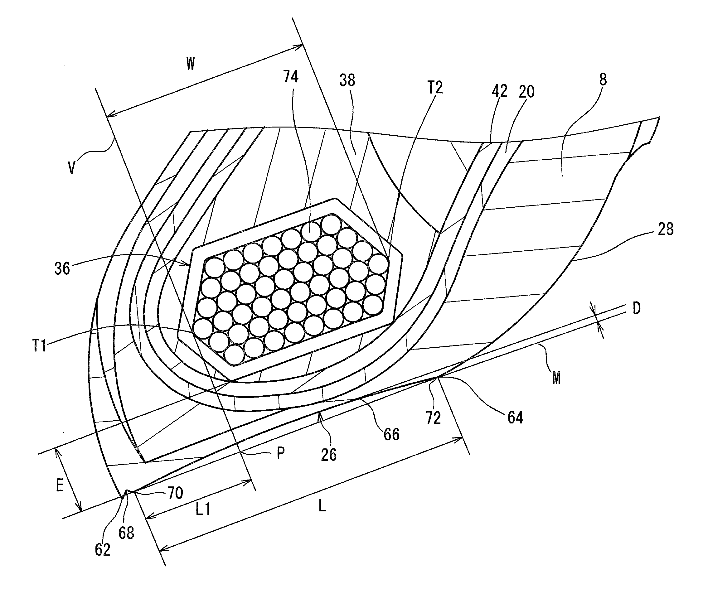
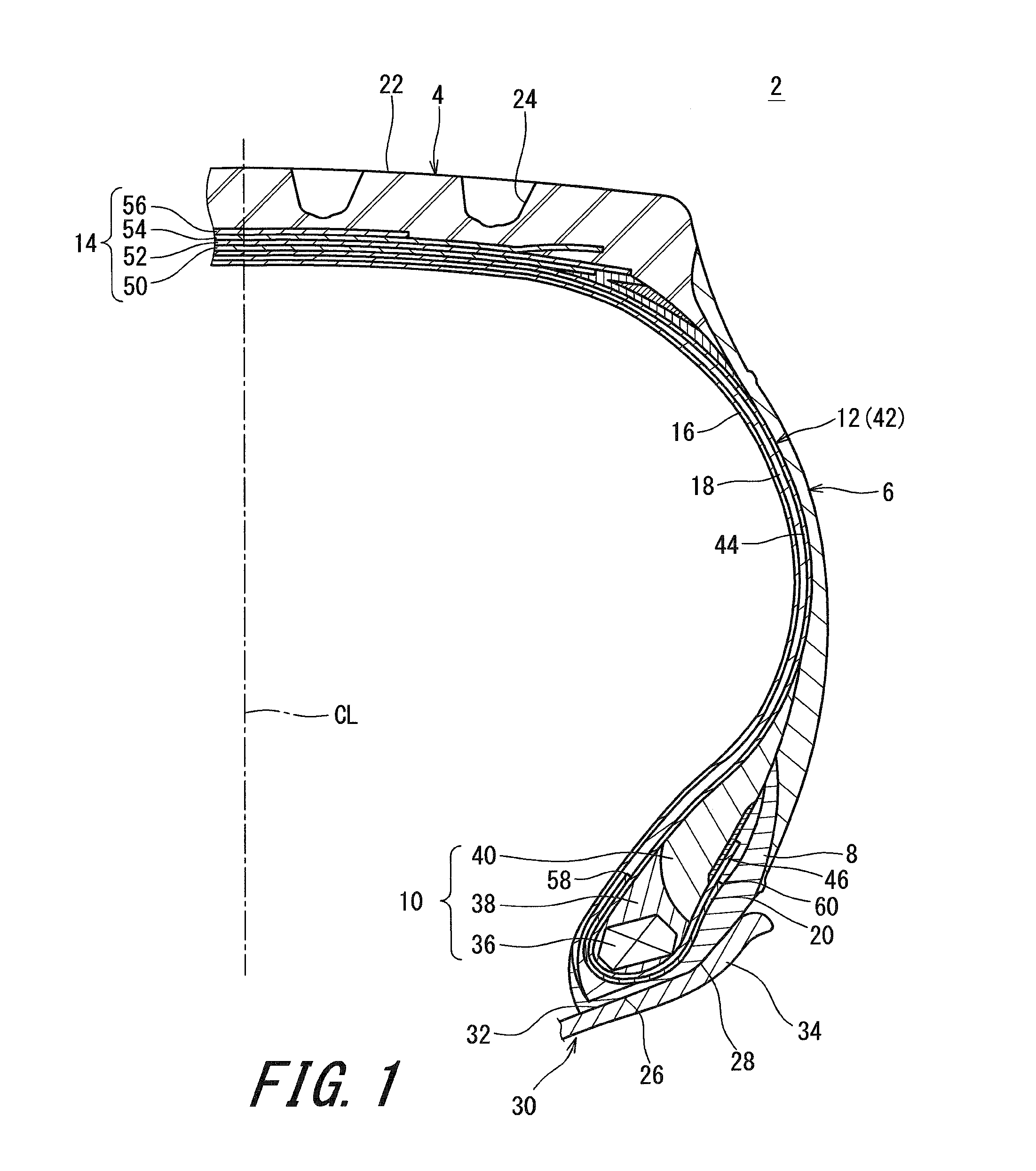
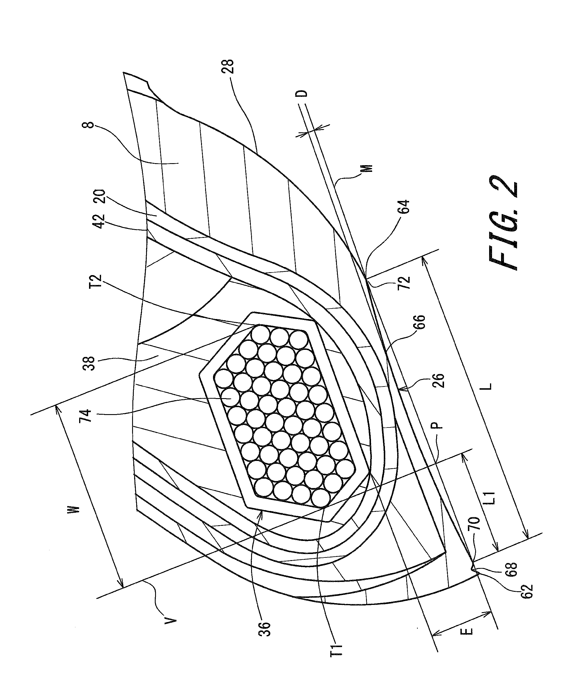
[0062]A tire of Example 1 having the structure shown in FIGS. 1 to 2 was obtained. The size of the tire was 11R22.5. The specifications of the tire are indicated in Table 1. In the tire, the width L of the depression was 24.3 mm, the width W of the core was 16.0 mm, and the distance L1 was 8.5 mm. The depression had an almost arc-shaped cross-section. Further, the distance E between the reference line M and the bottom surface of the core was 7.2 mm. An absolute value θ of an angle of each cord of the carcass ply relative to the equator plane was 90°.

examples 4 to 7

[0065]Tires of Examples 4 to 7 were each obtained in the same manner as in Example 1 except that the absolute value α had a value indicated in Table 2.

examples 8 to 11

[0066]Tires of Examples 8 to 11 were each obtained in the same manner as in Example 1 except that the hardness Hs had a value indicated in Table 3.

[0067][Fittability]

[0068]Mounting of the sample tire on a normal rim (7.50×22.5) and dismounting of the sample tire from the normal rim were performed by using a tire changer. A person who performed this work made a sensory evaluation as to whether or not the tire was easily mounted and dismounted. The results are indicated below in Tables 1 to 3 as an index value based on the value of Example 1. The greater the value is, the better the evaluation is.

[0069][Resistance to Waving]

[0070]The tire having been evaluated for the fittability was visually checked for waving in the bottom surface of the chafer. The results are indicated in Tables 1 to 3, and the evaluation is such that “A” represents a case where waving was not generated at all, “B” represents a case where, although generation of waving was found, the waving was generated at a stan...


PUM

PropertyMeasurementUnit
angleaaaaaaaaaa
angleaaaaaaaaaa
angleaaaaaaaaaa

Abstract

A tire 2 of the present invention includes a pair of fillers 20 turned up around beads 10. Each filler 20 has multiple cords made of steel and aligned with each other. In the tire 2, an outer surface of a chafer 8 has a bottom surface 26 that contacts with a seat surface of a rim 30. When a reference line M represents a straight line that contacts with the bottom surface 26 in a cross-section obtained by cutting the tire at the plane perpendicular to the circumferential direction, the bottom surface 26 has a depression 66 that is shaped so as to project radially outward of the reference line M. A ratio (D/L) of a maximum depth D of the depression 66 to a width L of the depression 66 is greater than or equal to 0.007 and not greater than 0.060.

Description

[0001]This application claims priority on Patent Application No. 2015-159290 filed in JAPAN on Aug. 12, 2015. The entire contents of this Japanese Patent Application are hereby incorporated by reference.BACKGROUND OF THE INVENTION[0002]Field of the Invention[0003]The present invention relates to pneumatic tires. More specifically, the present invention relates to heavy duty pneumatic tires that are to be mounted to vehicles such as trucks, buses, and the like.[0004]Description of the Related Art[0005]In a tire, bead portions are fitted into a rim. In a running state, the bead portions are under a heavy load. The bead portions are required to have durability for withstanding the load.[0006]The rim is fastened by the beads that are fitted into the rim. In order to prevent a tire from slipping on a rim, that is, prevent “slip on rim”, fastening force of the beads is required to be enhanced. Meanwhile, in order to easily mount the tire on the rim, a pressure at which the beads are fitte...

Claims


Application Information

Patent Timeline
Patent Type & Authority Applications(United States)
IPC IPC(8): B60C15/05
CPCB60C2015/0614B60C15/05B60C15/04B60C2015/046B60C15/024B60C2015/0692B60C2015/048B60C15/0607B60C2200/06
Inventor ITO, TADASHI
Owner SUMITOMO RUBBER IND LTD
Why Eureka
Try Eureka