
Backlight module with sealant covering gaps and display device comprising same

Active Publication Date: 2021-11-09
WUHAN CHINA STAR OPTOELECTRONICS TECH CO LTD
View PDF6 Cites 0 Cited by
  • Summary
  • Abstract
  • Description
  • Claims
  • Application Information

AI Technical Summary

Benefits of technology

The present invention provides a backlight module and display device to solve the problem of light leaking caused by conventional technology to increase screen-to-body ratio. By using an elastic adhesive to bond the uppermost diaphragm to a frame, the backlight module is isolated from outside environments and prevents foreign matter from entering during transportation and assembly processes. Additionally, the invention solves the problem of the overflowed adhesive leaking into the display region and affecting image quality during a drop test.

Problems solved by technology

Firstly, because the left side and the right side of the backlight module do not have the light-shading glue, foreign matter is prone to enter the backlight module during processes of transportation and assembly, which results in problems such as white spot, black spot, and scratch on the diaphragms.
Secondly, a thickness of the metal frame is usually only 0.1 mm after an adhesive is coated on lateral sides of the backlight module. A 0 to 0.05 mm gap usually exists between the metal frame and glass. Therefore, the adhesive is prone to overflow into the backlight module, which reduces the gap, leading to waving during temperature and humidity test. An overflowed adhesive is prone to leak into a display region and seriously affect image quality during a drop test.

Method used


Image

  • Backlight module with sealant covering gaps and display device comprising same
  • Backlight module with sealant covering gaps and display device comprising same

Examples


first embodiment

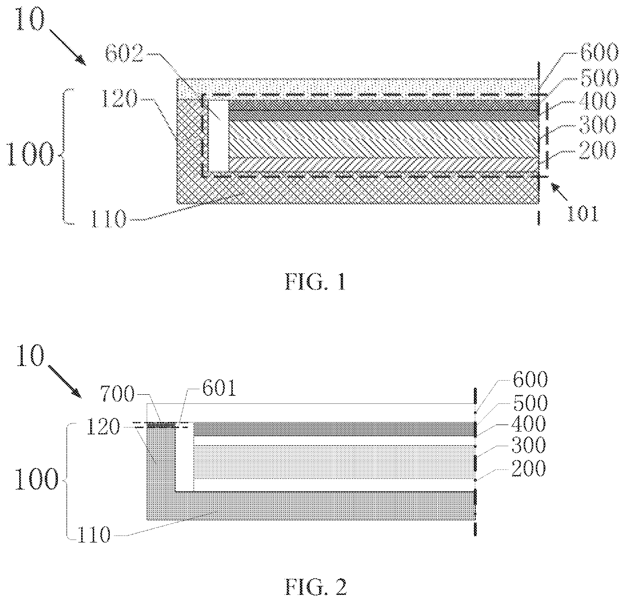
[0028]As shown in FIG. 1, in the present embodiment, a backlight module 10 provided by the present disclosure includes an outer housing 100, a reflective film 200, a light guide plate 300, a diffuser 400, a second brightness enhancement film (BEF) 500, and a first BEF 600.

[0029]The outer housing 100 is a metal housing, including a first housing 110 and a second housing 120. The second housing 120 is vertically connected to a periphery of the first housing 110. The first housing 110 and the second housing 120 encircle to form a cavity 101.

[0030]In the present embodiment, the backlight module 10 is a direct type backlight module, which emits light from its bottom. The direct type backlight module has advantages such as wider color gamut, more natural image effect, better uniform brightness on panel, and less light leakage of panel. Furthermore, contrast of the direct type backlight module can be improved to achieve dynamic intelligent backlight. The reflective film 200 is disposed in ...

second embodiment

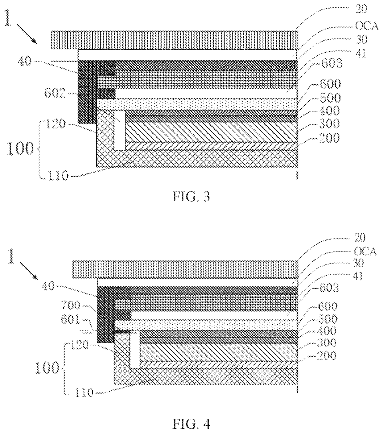
[0038]As shown in FIG. 3 and FIG. 4, in the present embodiment, a display device 1 provided by the present disclosure uses the backlight module 10 of the first embodiment. The display device 1 further includes a plate glass 20, an optically clear adhesive (OCA), a display panel 30, and a sealant 40.

[0039]The display panel 30 is disposed on the backlight module 10. A third gap 603 is defined between the display panel 30 and the backlight module 10. The backlight module 10 provides lighting source for the display panel 30 to display images.

[0040]The plate glass 20 is disposed on a side of the display panel 30 away from the backlight module 10, thereby protecting the display panel 30 and preventing the display panel 30 from being polluted or scratched by foreign matter.

[0041]The sealant 40 is a hot melt adhesive or an ultraviolet adhesive and is used to encapsulate the display panel 30, the backlight module 10, and the plate glass 20. Specifically, the sealant 40 covers the first gap 6...


PUM


Abstract

The disclosure provides a backlight module and a display device. The backlight module includes an outer housing, wherein the outer housing includes a first housing and a second housing vertically connected to a periphery of the first housing. The first housing and the second housing encircle to form a cavity. The backlight module further includes a first brightness enhancement film (BEF) disposed on the cavity, wherein the first BEF extends to the second housing. A lateral side of the first BEF near the first housing is aligned with an outer side of the second housing.

Description

RELATED APPLICATIONS[0001]This application is a National Phase of PCT Patent Application No. PCT / CN2019 / 108832 having International filing date of Sep. 29, 2019, which claims the benefit of priority of Chinese Patent Application No. 201910613803.7 filed on Jul. 9, 2019. The contents of the above applications are all incorporated by reference as if fully set forth herein in their entirety.FIELD AND BACKGROUND OF THE INVENTION[0002]The present disclosure relates to the display field and, more particularly, relates to a backlight module and a display device.[0003]Backlight modules, as a lighting source of liquid crystal displays (LCDs), are fixed on a backside of the LCDs. Luminous effect of the backlight modules directly affects visual effect of the LCDs. With development of technology, market demand for the LCDs as well as for the backlight modules becomes higher and higher.[0004]The backlight modules can be classified into edge type backlight modules and direct type backlight module...

Claims


Application Information

Patent Timeline
IPC IPC(8): G02F1/13357G02F1/1333F21V8/00
CPCG02F1/133311G02B6/0051G02B6/0053G02B6/0055G02B6/0088G02B6/0093G02F1/133602G02F1/133611G02F1/1333G02F1/133605G02F1/133606G02F1/133608G02B6/0081G02F1/133308G02F1/1336G02F2202/28G02F1/133545
Inventor LI, SHENGMINGLIU, JIAN
Owner WUHAN CHINA STAR OPTOELECTRONICS TECH CO LTD
Learn More