Optical transmission system using in-line amplifiers

a transmission system and amplifier technology, applied in optical transmission, electromagnetic transmission, electromagnetic transceivers, etc., can solve the problems of reducing s/n ratio, reducing s/n ratio, amplifying spontaneous emission lights, etc., to prevent the waveform of optical signals from being degraded, and reducing the cost of production.

Inactive Publication Date: 2006-12-21
FUJITSU LTD
View PDF24 Cites 0 Cited by
  • Summary
  • Abstract
  • Description
  • Claims
  • Application Information

AI Technical Summary

Benefits of technology

[0021] The object of the present invention is to provide a technology which can compensate for transmission degradation especially due to fiber dispersion, and ensure a good transmission characteristic for a longer distance, in an optical in-line amplifier system.
[0023] Since the non-linear effect that the optical signal receives on the transmission path corresponds to the blue chirping, this effect can be compensated for by performing red chirping whose α parameter is positive on the transmitting side. This leads to the effect of preventing the waveform of the optical signal from being degraded.
[0024] Furthermore, degradation of the optical signal can be prevented more effectively by setting the amount of dispersion compensation in order to compensate for the dispersion from a preceding transmission path, in each of the repeaters or the receiver.
[0025] With the above described configuration, an optical signal can be transmitted by performing red chirping to compensate for the non-linear effect in order to prevent a waveform from being degraded even if an optical output power is increased on the transmitting side.
[0026] Additionally, since the amount of dispersion compensation in a repeater or a receiver can be achieved from a combination of unit modules, implementation as a product is relatively easy.

Problems solved by technology

The system using in-line amplifiers, however, poses a new problem where amplified spontaneous emission lights, from plurality of amplifiers, due to the connection of the plurality of amplifiers, are accumulated, and the S / N ratio is lowered.
The lowering of the S / N ratio leads to the degradation of a minimum reception power of a receiver.
Accordingly, a reception waveform in an optical transmission system after fiber propagation varies depending on the chromatic dispersion, and a transmission error will occur depending on the degree of dispersion.
Accordingly, it becomes quite impossible to properly receive the optical signal on a receiving side unless suitable compensation is made.
1) Output of transmission power cannot be increased.
2) Dispersion-compensation on a transmitting side is ineffective.
Accordingly, the losses of dispersion-compensators become larger, and the tolerance of the losses becomes difficult as transmission distance is extended.
Lowering the level of an optical input to the O / E leads to degradation of reception sensitivity, and this imposes a limitation.
Furthermore, optical input power may sometimes have an upper limit depending on the dispersion-compensator to be used.

Method used


Image

  • Optical transmission system using in-line amplifiers
  • Optical transmission system using in-line amplifiers
  • Optical transmission system using in-line amplifiers

Examples


Embodiment Construction

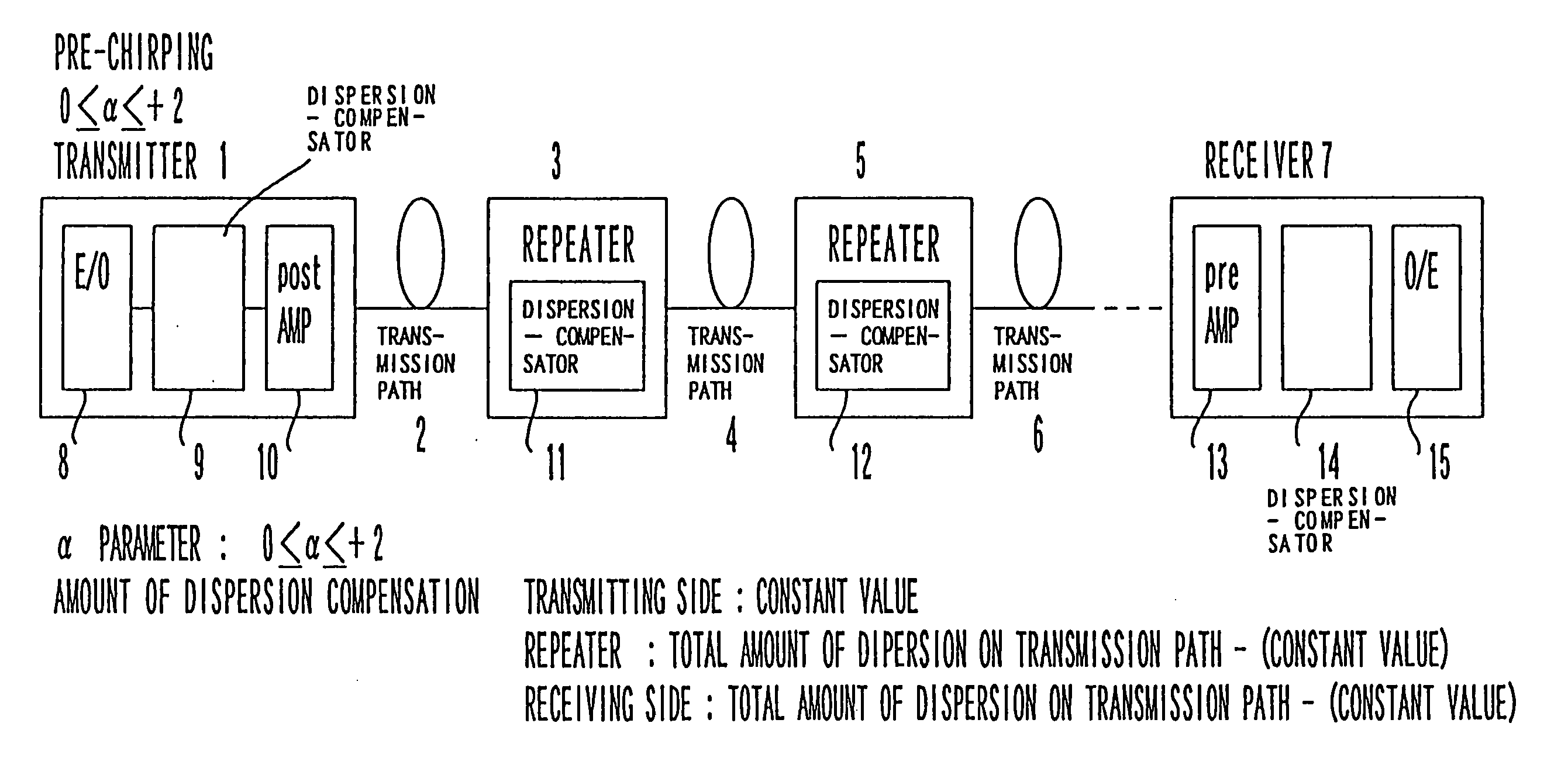
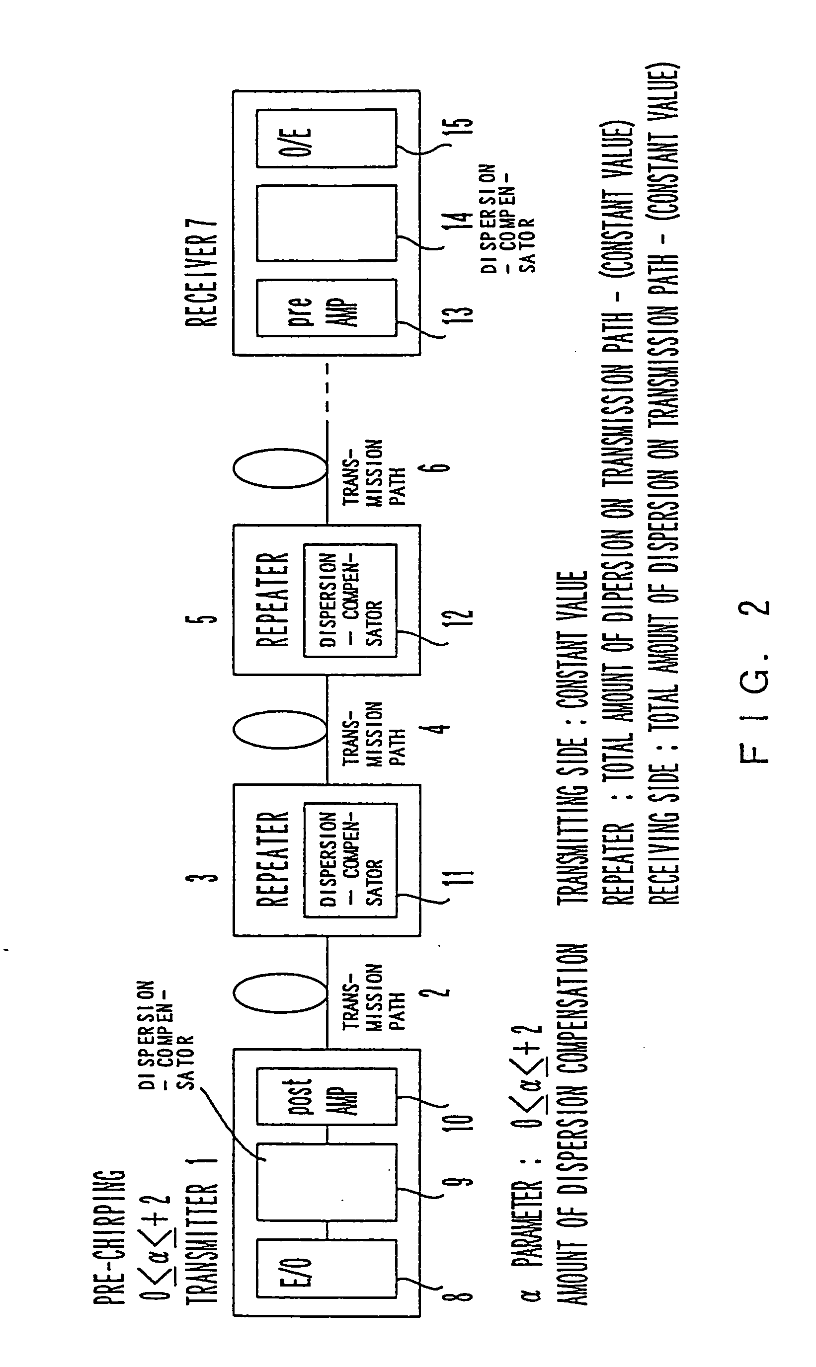
[0037]FIG. 2 is a schematic diagram showing the basic configuration of an optical transmission system according to an embodiment of the present invention.

[0038] In this figure, a transmitter 1 and a receiver 7 are connected by transmission paths 2, 4, 6, . . . and repeaters 3, 5, . . . . The transmitter 1 is composed of an E / O (Electric-to-optical signal converter) 8, a dispersion-compensator 9 and a post-amplifier 10. The E / O 8 is intended to convert an electric signal into an optical signal. The dispersion-compensator is intended to perform a predetermined amount of dispersion compensation on the side of the transmitter 1. The post-amplifier 10 is intended to amplify an optical output in order to allow the optical signal to be transmitted farther along a transmission path. In addition, red chirping whose α parameter ranges between 0 and +2 is performed on the side of the transmitter 1, according to the present invention. The amount of dispersion compensation of each of the disper...


PUM


Abstract

In a system connecting a transmitter and a receiver using transmission paths and repeaters (in-line amplifiers), red chirping whose α parameter is performed for an optical signal on a transmitting side. Each of the repeaters includes a dispersion-compensator for compensating the amount of dispersion on a preceding transmission path. The amount of dispersion compensation of the dispersion-compensator included in the transmitter is made constant. The dispersion-compensator included in the receiver is arranged in order to compensate the amount of dispersion on a preceding transmission path. A spread of a pulse width on a transmission path can be efficiently compensated by using the compensation capability of the dispersion-compensators and the red chirping on the transmitting side.

Description

CROSS-REFERENCE TO RELATED APPLICATIONS [0001] This application is a continuation of application Ser. No. 10 / 425,864 filed Apr. 30, 2003, which is a divisional of application Ser. No. 08 / 929,090, filed Sep. 15, 1997, now U.S. Pat. No. 6,570,691, which claims priority benefit to Japanese Application 09-044407 filed on Feb. 27, 1997.BACKGROUND OF THE INVENTION [0002] 1. Field of the Invention [0003] The present invention relates to an optical transmission system using fibers, and more particularly to an optical transmission system using in-line amplifiers. [0004] 2. Description of the Related Art [0005] An optical transmission system is now being developed with increased capacity and an extended span of transmission. An increase of a bit rate and wavelength division multiplexing system are now being discussed so as to increase capacity. In the meantime, an optical amplifier has been introduced so as to extend the span of transmission. The types of optical amplifiers include a post-amp...

Claims


Application Information

Patent Timeline
Patent Type & Authority Applications(United States)
IPC IPC(8): H04B10/12H04B10/2507H04B10/2519H04B10/2525H04B10/2543H04B10/40H04B10/50H04B10/60
CPCH01L31/14H04B10/25137H04B2210/256H04B2210/252H04B10/2543
Inventor MIYAUCHI, AKIRAYAMANE, KAZUOKAWASAKI, YUMIKOOKANO, SATORU
Owner FUJITSU LTD
Why Eureka
Try Eureka