
Toner supplier, development unit, and image forming apparatus

Inactive Publication Date: 2009-03-12
SHARP KK
View PDF3 Cites 0 Cited by
  • Summary
  • Abstract
  • Description
  • Claims
  • Application Information

AI Technical Summary

Benefits of technology

[0008]Because the melting point of the auxiliary member is higher than the melting points of the shaft and fixture, this member is not influenced by heat when the shaft and fixture are welded thermally to each other. This prevents the auxiliary member from waving when the shaft and fixture are welded thermally to each other. Because the shaft and fixture can melt sufficiently without the auxiliary member waving, the shaft and fixture can be welded firmly to the auxiliary member. Accordingly, the toner stirrer can be manufactured at a high yield with high part accuracy.

Problems solved by technology

The thermal welding is liable to cause defective calking, thereby resulting in a low manufacturing yield and low accuracy of parts.

Method used


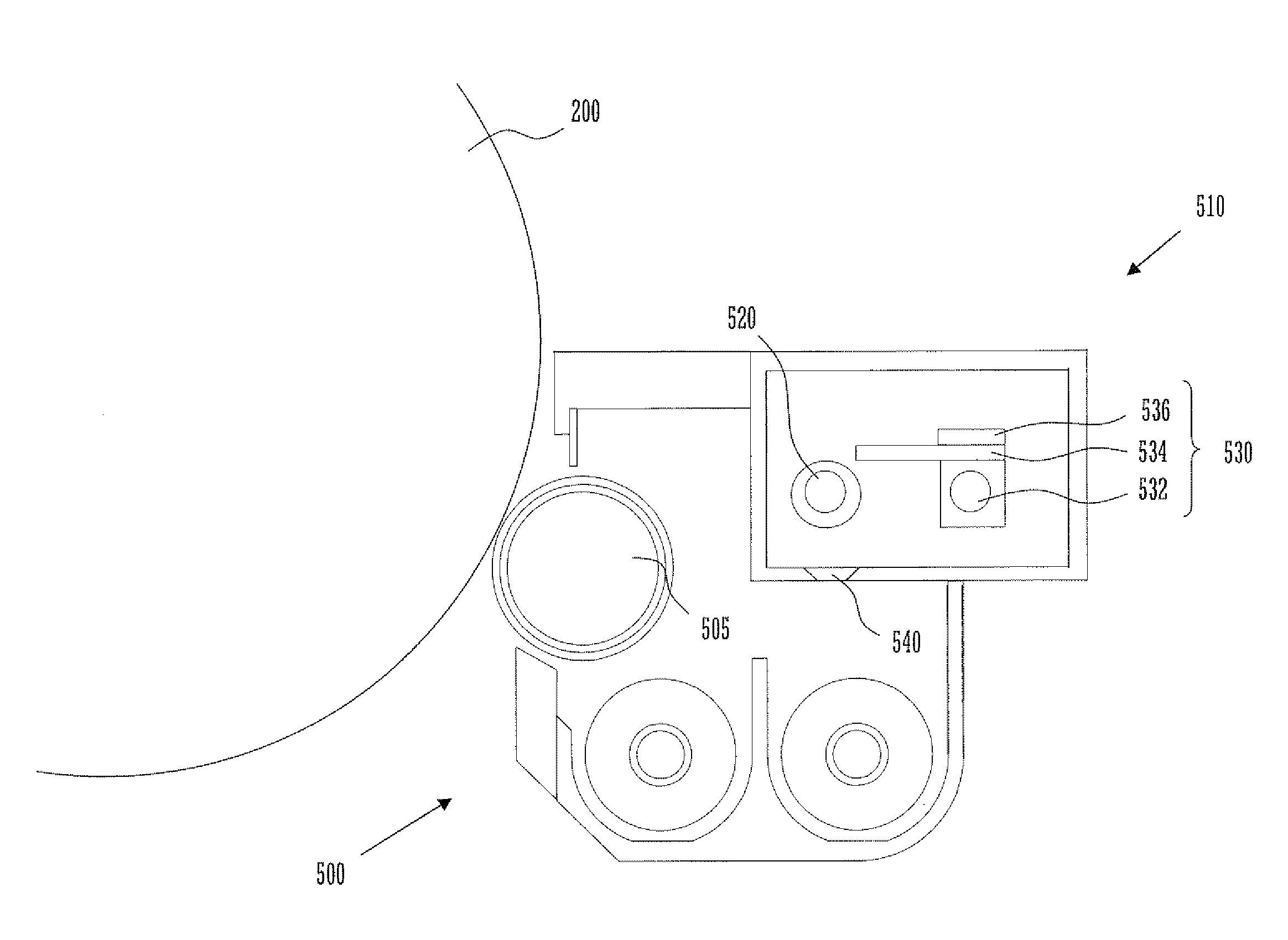
Image

  • Toner supplier, development unit, and image forming apparatus
  • Toner supplier, development unit, and image forming apparatus
  • Toner supplier, development unit, and image forming apparatus

Examples


Embodiment Construction

[0016]The best mode of carrying out the present invention will be described below in detail with reference to the accompanying drawings.

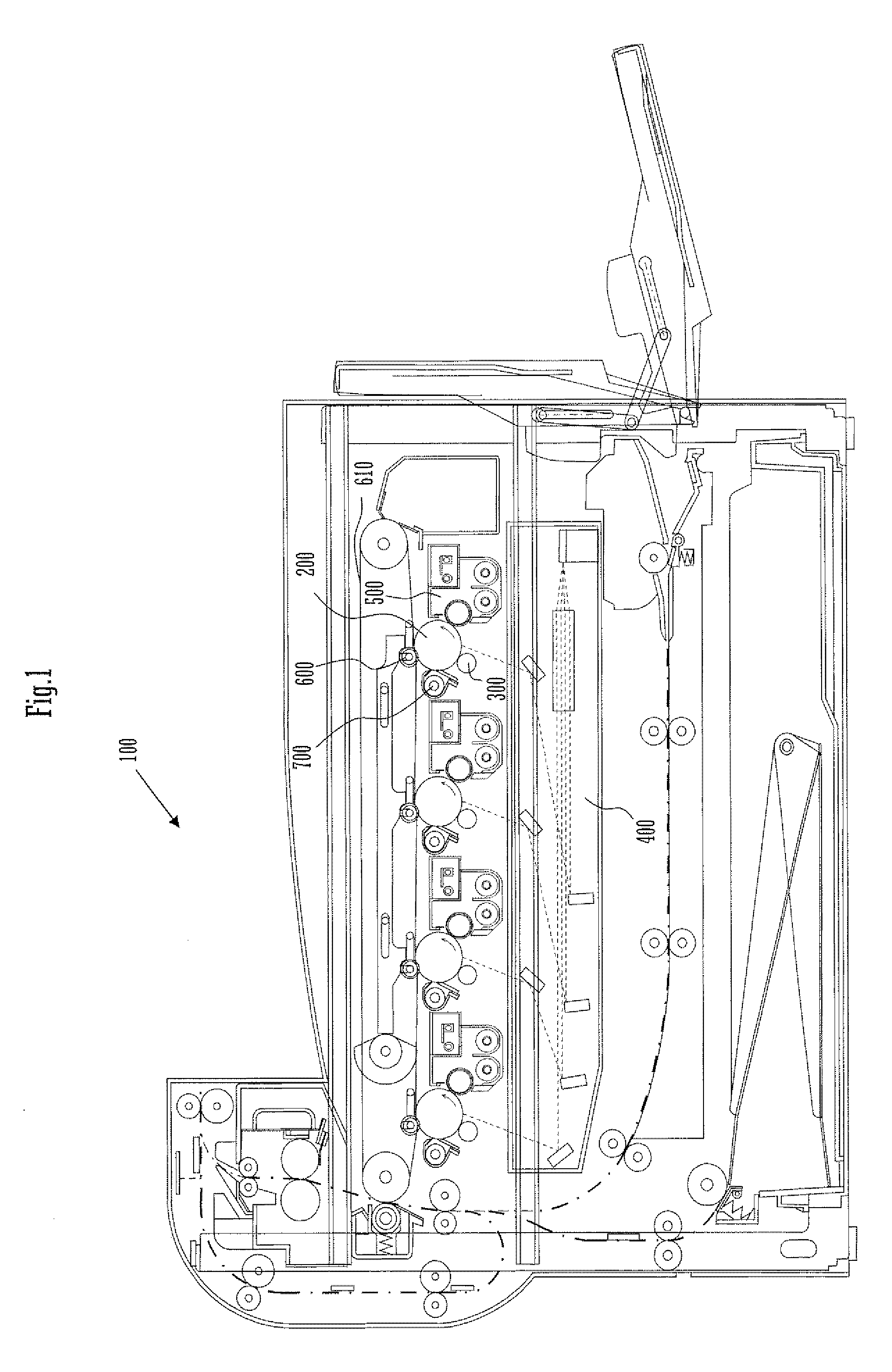
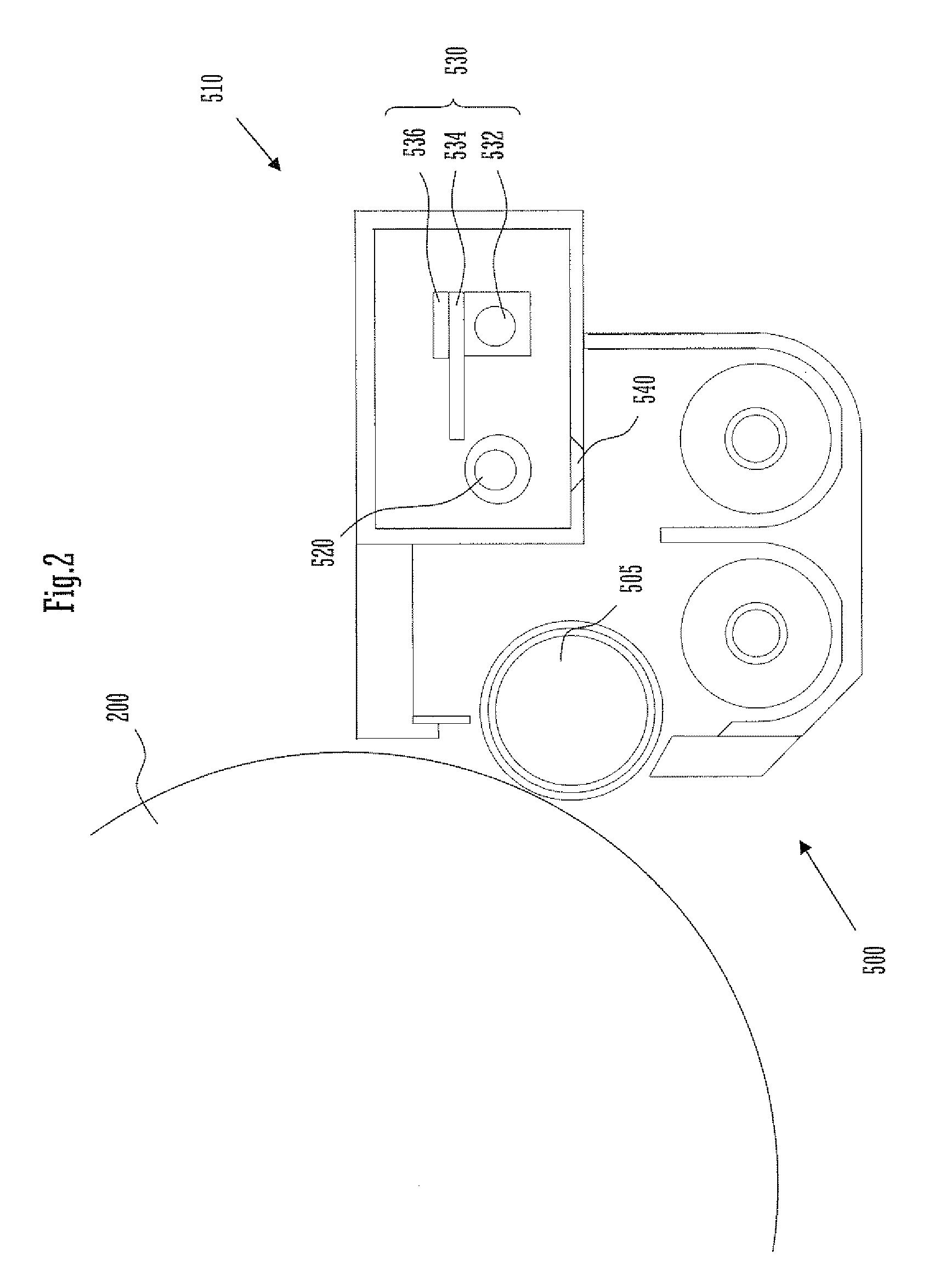
[0017]With reference to FIG. 1, an image forming apparatus 100 embodying the present invention includes a photosensitive drum 200, a charger 300, an exposure unit 400, a development unit 500, an intermediate transfer roller 600, an intermediate transfer belt 610, and a cleaner 700.

[0018]The charger 300 charges the cylindrical surface of the photosensitive drum 200 uniformly to a preset electric potential. The exposure unit 400 exposes the drum surface to light based on image data. The exposure forms an electrostatic latent image on the drum surface. The development unit 500 includes a development roller 505, which carries toner on its cylindrical surface and makes the latent image visible with the toner. The intermediate transfer roller 600 gives a transfer bias for transferring the toner image on the drum surface onto the intermediate transfer belt...


PUM


Abstract

A toner supplier according to the present invention includes a toner stirrer. The toner stirrer includes a shaft, an auxiliary member, and a fixture. The melting point of the auxiliary member is higher than the melting points of the shaft and fixture. The shaft and fixture are welded to each other with the auxiliary member interposed between them.Because the melting point of the auxiliary member is higher than the melting points of the shaft and fixture, this member is not influenced by heat when the shaft and fixture are welded thermally to each other.

Description

CROSS REFERENCE[0001]This Nonprovisional application claims priority under 35 U.S.C. §119(a) on Patent Application No. 2007-233575 filed in Japan on Sep. 10, 2007, the entire contents of which are hereby incorporated by reference.BACKGROUND OF THE INVENTION[0002]The present invention relates to a toner supplier including a toner stirrer. The invention also relates to a development unit including such a toner supplier. The invention further relates to an image forming apparatus including such a development unit.[0003]In general, a toner supplier includes a toner container and a toner stirrer, which includes a shaft and an auxiliary member. The shaft needs to be strong enough to support the auxiliary member stirring the toner in the container. The auxiliary member needs to be strong enough to stir the toner, and be flexible when this member comes into contact with a wall of the container. Therefore, the shaft and the auxiliary member are made of different materials.[0004]JP 2004-28693...

Claims


Application Information

Patent Timeline
IPC IPC(8): G03G15/08
CPCG03G2215/0819G03G15/0872G03G15/0877G03G2215/0855
Inventor WAKABAYASHI, TAKESHIDEGUCHI, MASANOBUOKUDA, TAKESHI
Owner SHARP KK
Learn More