Dental implants

a technology of dental implants and implants, applied in dental implants, dental surgery, medical science, etc., can solve the problems of affecting the treatment effect of patients, so as to achieve the effect of easy separation, easy detection of separation state, and easy and convenient progress

Inactive Publication Date: 2020-10-08
LIEBHERR VERZAHNTECHNIK GMBH
View PDF0 Cites 0 Cited by
  • Summary
  • Abstract
  • Description
  • Claims
  • Application Information

AI Technical Summary

Benefits of technology

[0025]According to the present invention, the present invention includes a first corresponding coupling part that mainly performs a rotation prevention function formed in a lower part of an abutment, and a first coupling part formed in an axial hole inner surface of a fixture at a position that is in association with the first corresponding coupling part so that the first coupling part is complementarily coupled with the first corresponding coupling part.
[0026]Accordingly, according to the present invention, in the process of separating the abutment from the fixture, the abutment and the fixture are easily separated by pulling lightly upwardly the abutment from the fixture since the first corresponding coupling part is separated from the first coupling part when the abutment is rotated with respect to the fixture.
[0027]In addition, according to the present invention, an inclined surface may be provided on the inner surface of the axial hole of the fixture except for a region of the inner surface in which the first coupling part is provided, such that an inner diameter of the inclined surface continuously decreases in a bottom direction. When a coupling protrusion of the first corresponding coupling part is released from the coupling recess of the first coupling part by rotation of the abutment in the circumferential direction, the coupling protrusion of the first corresponding coupling part pushes the abutment upwards from the fixture due to elastic repulsion from the inclined surface of the inner surface of the axial hole of the fixture, thereby automatically decoupling the abutment and the fixture from each other.
[0028]In addition, in the present invention, the abutment is not re-coupled with the fixture under excessive rotation since the abutment is automatically and upwardly pushed when the abutment is rotated with respect to the fixture.
[0029]In addition, according to the present invention, in the process of separating the abutment from the fixture, the abutment is automatically separated from the fixture by being upwardly protruded from the fixture when the abutment is rotated with respect to the fixture. Accordingly, the operator may easily detect a separation state between the abutment and the fixture. Thus, the implant procedure may easily and conveniently progress without difficulty and worry. In addition, according to the present invention, an additional polygonal form for a rotation prevention function is not provided to the abutment. In addition, according to the present invention, when vertical occlusal force is applied to the abutment, the inclined surface may effectively absorb vertical occlusal pressure.
[0030]In addition, according to the present invention, the linear or spiral slit is provided in a portion between the top portion and the bottom portion of the abutment coupled to the fixture, such that the abutment has a function of absorbing a significant amount of external force, including chewing pressure, applied to the implant. It is therefore possible to distribute stress applied to the abutment across entire portions thereof and prevent stress from being concentrated in a specific portion of the abutment. It is also possible to significantly improve the sensation of chewing and endurance of the implanted tooth.

Problems solved by technology

In other words, the artificial tooth shakes, thus the implant user may not easily chew the food, and undesirable mastication pressure may occur around the artificial tooth.
Accordingly, the artificial tooth and the alveolar bone may be damaged.
In addition, an implant unit having the above conventional implant structure has many difficulties in coupling the screw within a narrow oral cavity.
Particularly, in the case of a patient whose surgical area is located on the back teeth side or who cannot widen his or her mouth widely, the implant procedure becomes more difficult.
However, the above elastic coupling structures between the fixture and the abutment of the conventional technique cause inconvenience when separating the abutment from the fixture, and are not able to effectively perform buffer functions when vertical occlusal force is applied.
However, upwardly pulling the abutment with respect to the fixture by force as described above may apply large force to the alveolar bone of the patient through the fixture.
As a result, there is great risk of damaging the alveolar bone of the patient due to excessive force.
However, when the fixture is deeply implanted from the top of the alveolar bone, the extraction device may not be used or applied.
In addition, in the conventional technique described above, the operator may require a large force to upwardly pull the abutment with respect to the fixture y force, and such a procedure may act as a considerable mental burden on the implant procedure.
In addition, in the conventional technique described above, the implant structure may perform a buffer function for horizontal pressure, but a buffer function for vertical occlusion pressure may not be performed.

Method used


Image

  • Dental implants
  • Dental implants
  • Dental implants

Examples


Embodiment Construction

[0046]Hereinafter, preferred embodiments of the present invention will be described in detail with reference to the accompanied drawings.

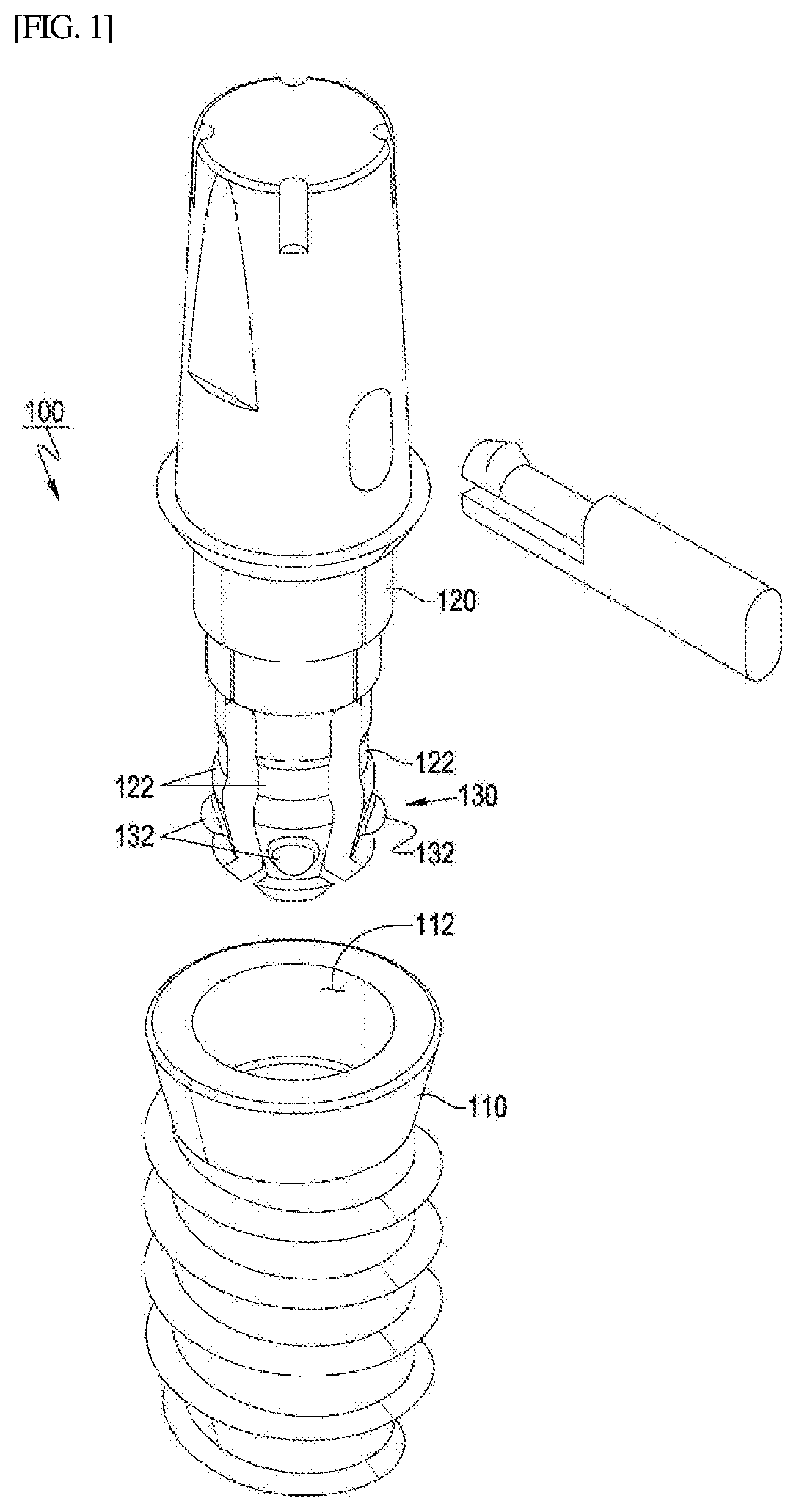
[0047]The dental implant 100 according to the present invention comprises a fixture 110 forming an artificial tooth root implanted in an alveolar bone (not shown), and an abutment 120 coupled with the fixture 110 at a low part thereof and coupled with a prosthesis (crown or denture) at an upper part thereof.

[0048]An implant procedure is performed by elastically and detachably coupling the fixture 110 and the abutment 120 as shown in FIG. 1 and FIG. 2.

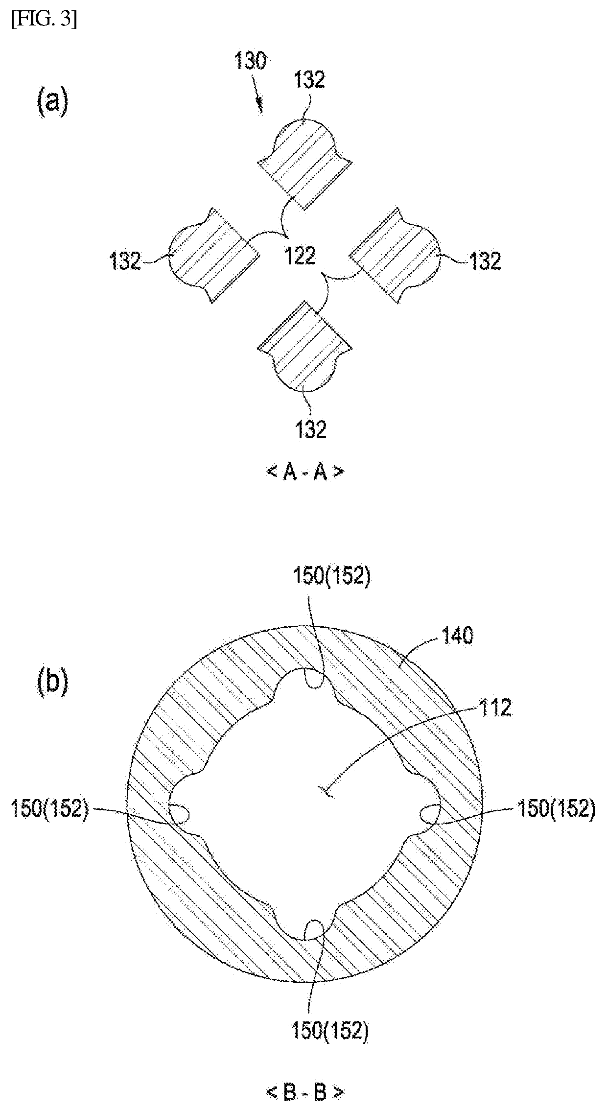
[0049]The dental implant 100 according to the present invention is formed in at least one coupling leg 122 that is formed in a lower part of the abutment 120 and inserted into the fixture 110. The dental implant 100 includes at least one first corresponding coupling part 130 that mainly performs a rotation prevention function with respect to rotation force less than a predetermined value. The first cor...


PUM


Abstract

The present invention provides a dental implant comprising: a first coupling part 150 is provided on an inner surface of the axial hole of the fixture, the first coupling part comprising a coupling recess depressed outward, in a predetermined location on the inner surface of the axial hole, and a first corresponding coupling part provided on an outer circumferential surface of the coupling leg 122 to be complementarily coupled to the first coupling part 150, the first corresponding coupling part comprising a coupling protrusion, wherein, in a state in which the abutment is fitted into the fixture by complementary coupling between the first coupling part and the first corresponding coupling part; when a rotation force applied to the abutment has less than a predetermined level, the abutment is prevented from rotating relative to the fixture in a circumferential direction, and when the rotation force applied to the abutment is equal to or greater than the predetermined level, the coupling leg of the abutment is elastically bendable radially inwardly toward a central axis and the abutment is rotated in the circumferential direction, allowing the coupling protrusion of the first corresponding coupling part to be released from the coupling recess of the first coupling part, so that the fixture and the abutment are decoupled from each other.

Description

CROSS REFERENCE TO RELATED APPLICATIONS[0001]This application is a 371 application for international patent application PCT / KR2018 / 000694 having the same title and is related to and claims priority from Korea Patent Application 10-2017-0006425 filed Jan. 13, 2017 which is incorporated herein by reference in its entirety.TECHNICAL FIELD[0002]The present invention relates to a dental implant implanted in the alveolar bone to form an artificial tooth. More particularly, the present invention relates to a dental implant whereby an abutment is easily separated from a fixture of the dental implant, and vertical occlusal force applied thereto may be efficiently absorbed by improving a coupling structure between the fixture and the abutment.BACKGROUND ART[0003]In dentistry, an implant means an artificial tooth substituting for a lost natural tooth or a dental procedure that is conducted in such a manner that a fixture is implanted into a jawbone to be fused with the jawbone for a predetermi...

Claims


Application Information

Patent Timeline
Patent Type & Authority Applications(United States)
IPC IPC(8): A61C8/00
CPCA61C8/0057A61C8/0074A61C8/0086A61C8/0056A61C8/0062A61C8/0065
Inventor KIM, HYUNG WOO
Owner LIEBHERR VERZAHNTECHNIK GMBH
Why Eureka
Try Eureka