Sutureless vascular anastomosis connection

a vascular anastomosis and sutureless technology, applied in the field of anastomosis, can solve the problems of affecting the general health of patients, affecting the treatment effect, and requiring a high degree of surgical skill and a considerable amount of time and patience from the surgeon

Active Publication Date: 2012-05-17
ASFORA IP +1
View PDF22 Cites 9 Cited by
  • Summary
  • Abstract
  • Description
  • Claims
  • Application Information

AI Technical Summary

Problems solved by technology

This interruption of flow, if too long, causes detrimental effects to organs and surrounding tissue, which can endanger, jeopardize, or worsen a patient's general health.
This process is not only difficult, time consuming, and expensive, but also requires a high degree of surgical skill and a considerable amount of time and patience from a surgeon.
Additionally, the use of sutures introduces a potential weakness in a surgical connection placed to connect two or more vessels, often resulting in tearing or leakage.
A leak resulting from poor or weakened sutures can create a number of problems such as internal hemorrhaging for the patient, requiring additional surgeries, time, and expense.
Also problematic are conventional connectors used in anastomosis procedures that are often bulky, unwieldy, or difficult to use, typically requiring significant skill and specialized equipment that can be expensive to manufacture and purchase.
Further, the time required for submission, review, and governmental approval of applications for the use of elaborate medical devices in humans for anastomosis applications is substantial, incurring significant social and health care costs due to the delay.
Some conventional solutions used in applications such as side-to-end vascular anastomosis often require more time, expertise, and effort since joining an end of a vessel to a side of another vessel is more time-consuming and skill-intensive than joining an end of a vessel to an end of another vessel.

Method used


Image

  • Sutureless vascular anastomosis connection
  • Sutureless vascular anastomosis connection
  • Sutureless vascular anastomosis connection

Examples


Embodiment Construction

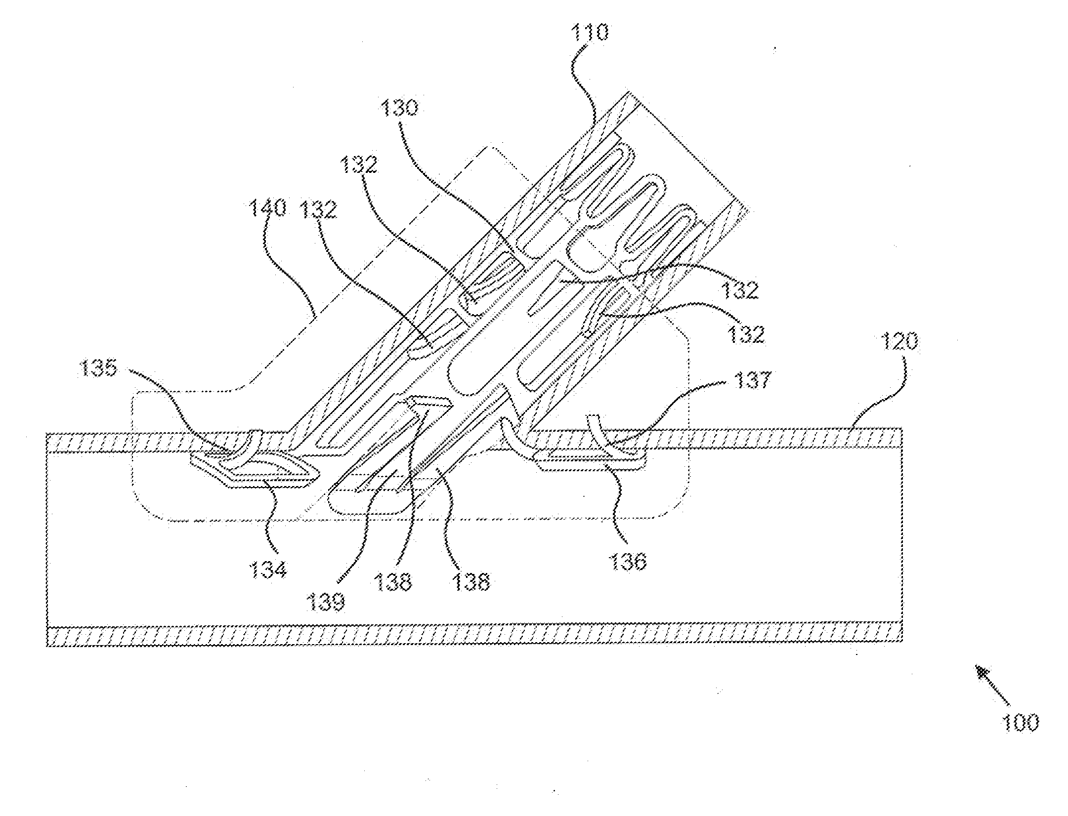
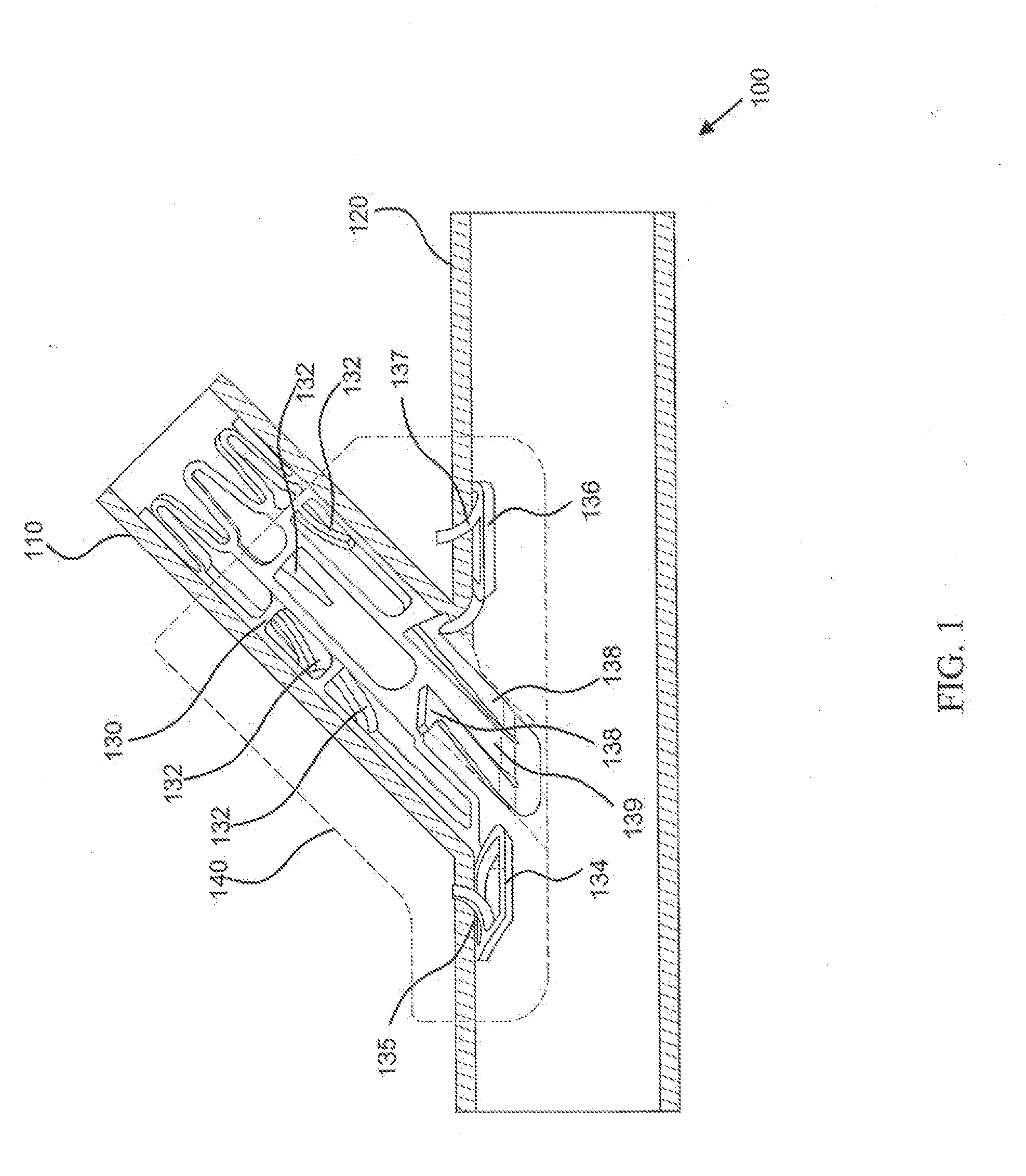
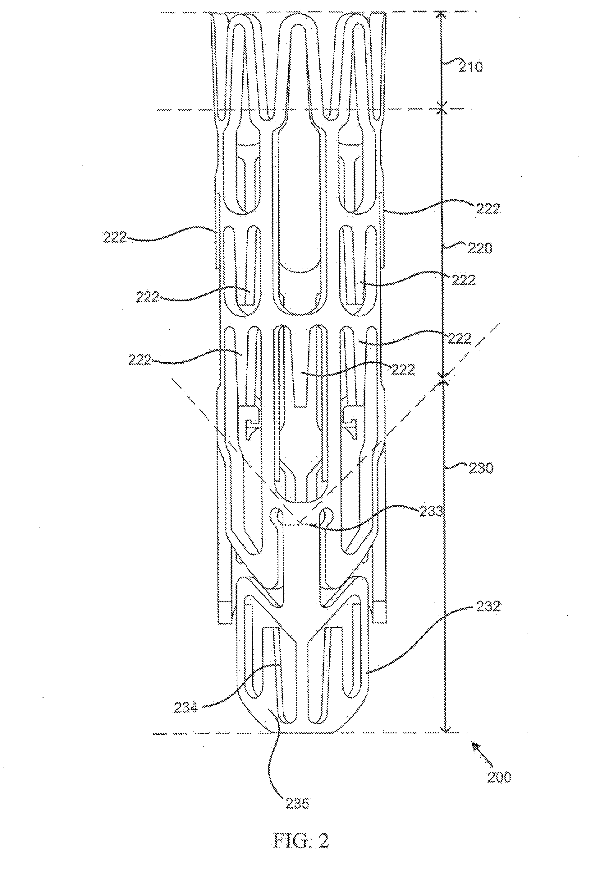
[0045]Embodiments or examples of the invention may be implemented in numerous ways, including as an apparatus, system, or process. A detailed description of one or more examples is provided below along with accompanying figures. The detailed description is provided in connection with such examples, but is not limited to any particular example. The scope is limited by the claims, but numerous alternatives, modifications, and equivalents are encompassed. Numerous specific details are set forth in the following description in order to provide a thorough understanding. These details are provided for the purpose of example and the descriptions provided may be used for implementation according to the claims without some or all of these specific details. For the purpose of clarity, technical material that is known in the technical fields related to the examples has not been described in detail to avoid unnecessarily obscuring the description.

[0046]Various techniques and devices for suturel...


PUM


Abstract

Techniques for sutureless vascular anastomosis are described, including a sutureless vascular anastomosis connector configured to couple a graft vessel to a main vessel, including a connector body configured to engage a main vessel when inserted into an opening in a wall of the main vessel, and a wing coupled to the connector body and formed using a memory material, the wing being configured to rotate about a transverse axis of the connector when a restraining force is removed from an exterior surface of the wing.

Description

CROSS-REFERENCE TO RELATED APPLICATIONS[0001]This application is a continuation of U.S. patent application Ser. No. 12 / 944,614 filed Nov. 11, 2010 (Attorney Docket No. MED-006) entitled “SUTURELESS VASCULAR ANASTOMOSIS CONNECTION,” related to co-pending U.S. patent application Ser. No. 12 / 946,703 filed Nov. 15, 2010 (Attorney Docket No. MED-006CON1) entitled “SUTURELESS VASCULAR ANASTOMOSIS CONNECTION,” which is a continuation of U.S. patent application Ser. No. 12 / 944,614, and related to co-pending U.S. patent application Ser. No. 12 / 981,406 filed Dec. 29, 2010 (Attorney Docket No. MED-006CON2) entitled “SUTURELESS VASCULAR ANASTOMOSIS CONNECTION,” which is a continuation of U.S. patent application Ser. No. 12 / 944,614, all of which are herein incorporated by reference for all purposes.FIELD OF THE INVENTION[0002]The present invention relates generally to anastomosis, and more specifically, to techniques for sutureless vascular anastomosis.BACKGROUND OF THE INVENTION[0003]Generally,...

Claims


Application Information

Patent Timeline
Patent Type & Authority Applications(United States)
IPC IPC(8): A61B17/11A61F2/06
CPCA61B17/08A61B17/10A61B17/11A61B17/56A61F2220/0016A61B2017/1107A61B2017/1135A61B2019/4857A61F2/064A61B2017/00867A61B2017/00946A61B2090/0811
Inventor ASFORA, WILSON THEOPHILOROBERTS, THOMAS ALBERTMIDDLEBUSHER, DUANE LEEPHIPPS, RICHARD DEANVILLALTA, MICHAEL EDWARDCARMACK, LEE JAMES
Owner ASFORA IP
Why Eureka
Try Eureka