Method and Apparatus for Monitoring Zones

a technology for monitoring zones and methods, applied in the field of monitoring zones, can solve problems such as new challenges, optical shadowing, and obstruction removal not always viable or even possible, and achieve the effect of introducing new challenges

Inactive Publication Date: 2012-05-17
OMRON SCI TECH
View PDF1 Cites 55 Cited by
  • Summary
  • Abstract
  • Description
  • Claims
  • Application Information

AI Technical Summary

Benefits of technology

[0012]The control unit further includes one or more processing circuits configured to control the outputs according to a defined control unit configuration, wherein the control unit configuration defines control responses for the sensors. In this regard, the control unit configuration data defines the control response for each sensor, such that the control unit may be understood as mapping or otherwise associating each sensor with one or more particular ones of the outputs, according to the defined control unit configuration. This feature allows the control unit to behave differently with respect to each sensor or with respect to different groups of its sensors. For example, the control response configured for each sensor defines how the control unit controls its outputs and / or which outputs it controls, on a per-sensor or per sensor group basis. Consequently, a user can configure different behavior (control responses) for intrusion detection and other events reported from the sensors, on a per sensor or sensor-group basis.

Problems solved by technology

Note that when the sensor is operated from a distance, the problem of optical shadowing must be considered, as it is often the case that overhead beams, gantries, cables, or other structures exist in the view of monitored areas.
Removing such obstructions represents an obvious solution to such shadowing problems, but obstruction removal is not always viable or even possible.
As with many solutions, however, the solution itself introduces new challenges.
Consequently, vision systems that use multiple sensors have very high overall processing burdens.
That burden ultimately causes the control unit cost and performance to scale with the number of sensors used in the application.
In turn, the need for high-performance vision processing makes it difficult for the customer to scale a solution to properly match to the monitoring task.
Another problem is that each sensor in a multi-sensor system is commonly provided with its own I / O.

Method used


Image

  • Method and Apparatus for Monitoring Zones
  • Method and Apparatus for Monitoring Zones
  • Method and Apparatus for Monitoring Zones

Examples


Embodiment Construction

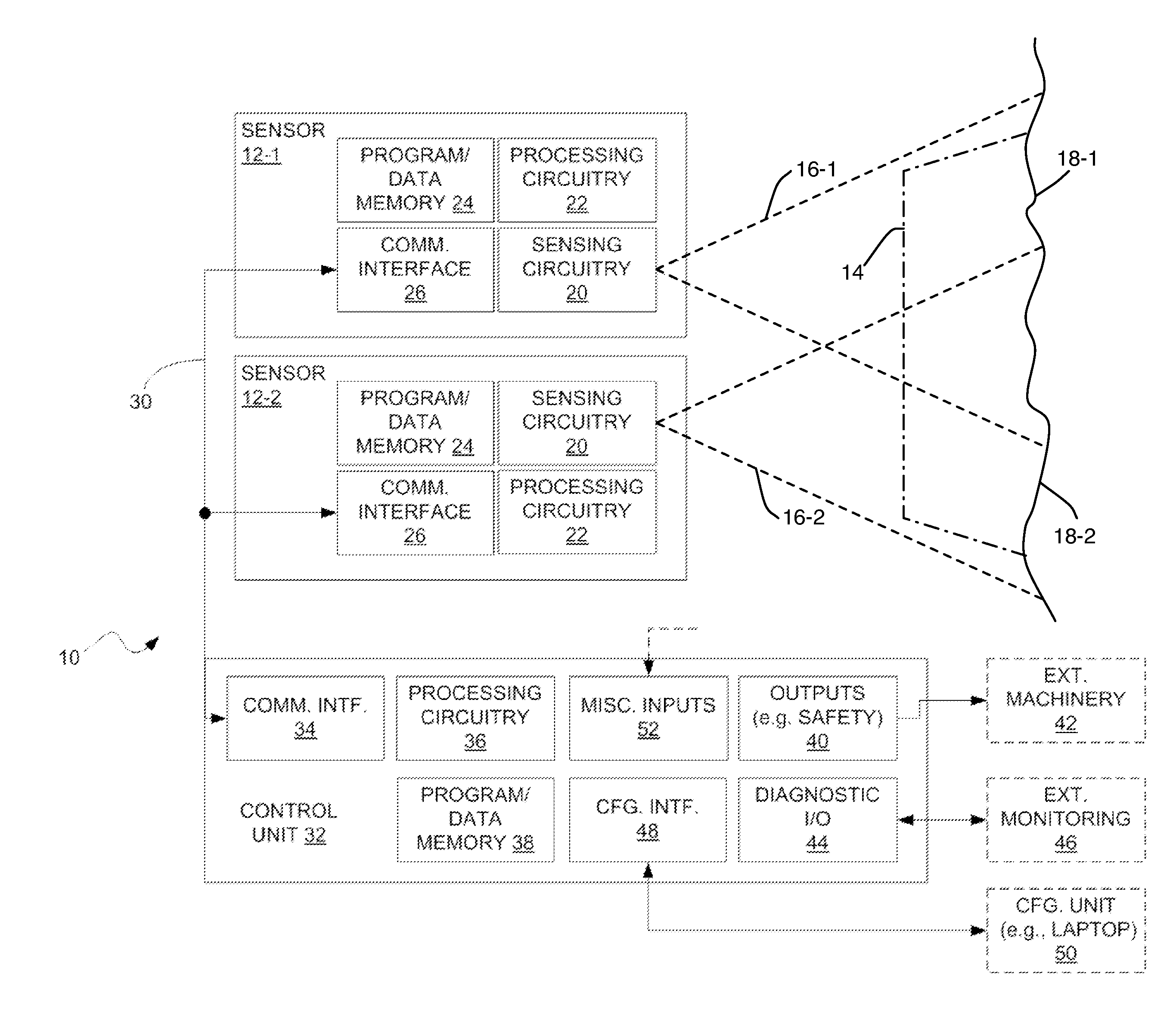
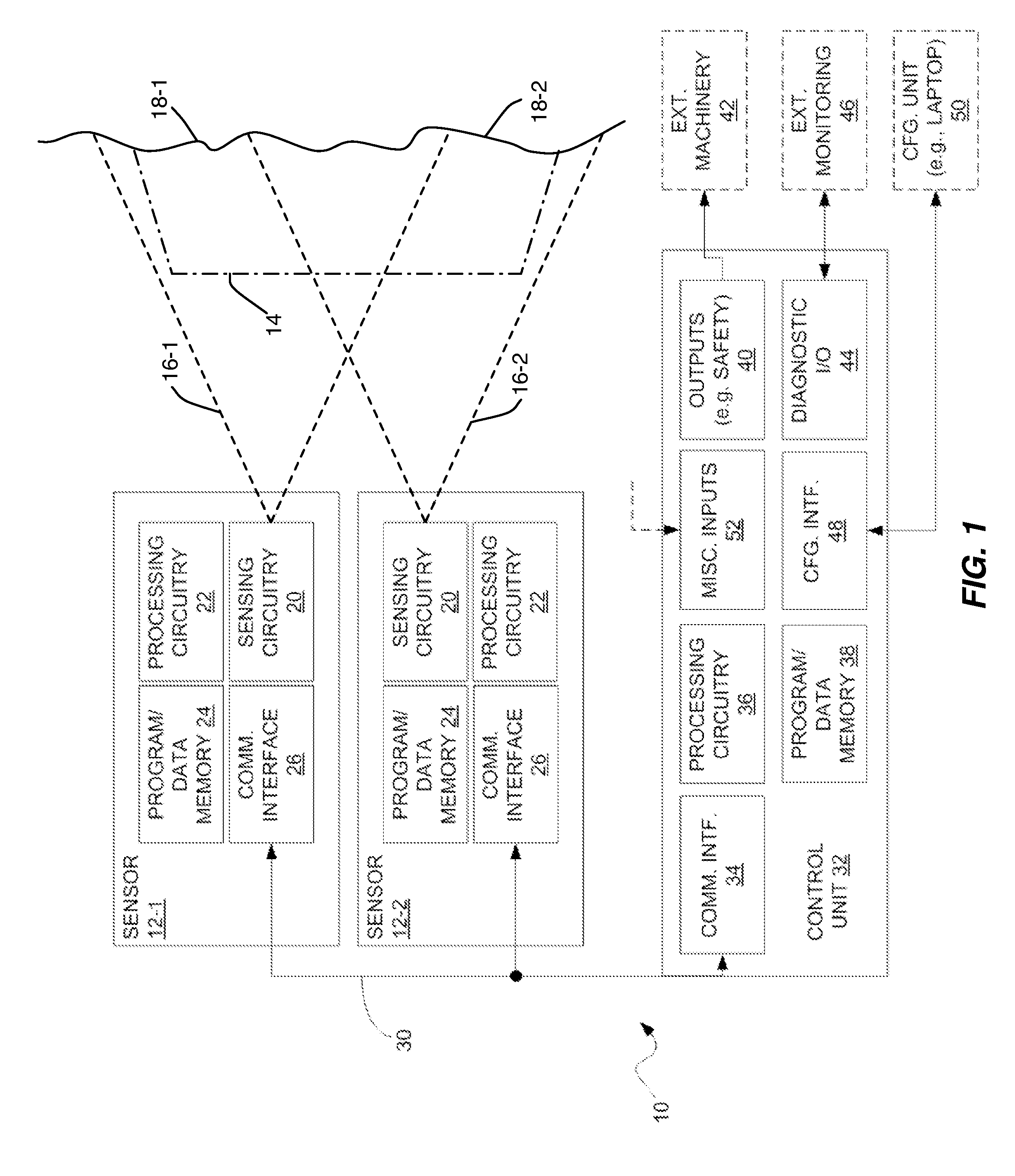
[0020]FIG. 1 illustrates a monitoring apparatus 10 (hereafter “apparatus 10”) as contemplated herein, according to one example embodiment. The apparatus 10 may be understood as a type of monitoring system, a plurality of sensors 12 are configured to monitor all or part of a monitoring zone 14. Here, the “monitoring zone”14 comprises a contiguous or non-contiguous two-dimensional area or three-dimensional volume to be monitored collectively by the sensors 12. Note that two sensors 12-1, and 12-2 are shown by way of example, but more sensors 12 could be used and further note that “sensors 12” is used in the generic plural sense and “sensor 12” is used in the generic singular sense.

[0021]As one example, the monitoring zone 14 is a more or less continuous three-dimensional space, but it includes obstructions or features that prevent a single sensor 12 from “seeing” the entire space. Therefore, by using two or more sensors 12, each having a different field of view 16 into the monitoring ...


PUM


Abstract

The present invention comprises an apparatus and method for monitoring a zone, which is a contiguous or non-contiguous, two-dimensional (2D) area or three-dimensional (3D) volume. Among its several advantages, the apparatus includes a plurality of sensors that monitor portions of the zone and report intrusion status to a control unit that provides monitoring boundary information to each of the sensors based on user input and further “maps” or otherwise associates each sensor to control unit outputs in accordance with user-defined behaviors. Still further, as a meaningful aid for configuring monitoring boundaries used by the sensors for objection intrusion detection, in one or more embodiments of the apparatus and method, at least a subset of sensors use a common coordinate frame of reference, based on a common origin located within overlapping sensor fields of view.

Description

RELATED APPLICATIONS[0001]This application claims priority under 35 U.S.C. §119 from the U.S. provisional patent application 61 / 414,761, which was filed on 17 Nov. 2010, and which is incorporated by reference herein.TECHNICAL FIELD[0002]The present invention generally relates to monitoring zones, such as the area or volume around a hazardous machine, secure location, or Autonomous Guided Vehicle (AGV), and particularly relates to the use of multiple sensors for zone monitoring.BACKGROUND[0003]Monitoring systems, such as laser scanners and stereoscopic camera systems, are often used for monitoring a zone established by configured boundaries. During run time, such systems detect the presence and measure the positions of objects bigger than a minimum object detection size, and compare these positions with the configured monitoring boundaries. Such a monitoring system then “decides” whether or not an intrusion has occurred for each considered boundary. Illumination of the area, whether ...

Claims


Application Information

Patent Timeline
Patent Type & Authority Applications(United States)
IPC IPC(8): G05B11/01
CPCF16P3/144G08B13/19641G08B13/19652F16P3/142H04N7/181H04N7/185G08B13/1968
Inventor DRINKARD, JOHN
Owner OMRON SCI TECH
Why Eureka
Try Eureka