
Variable compression ratio apparatus

Inactive Publication Date: 2012-05-24
HYUNDAI MOTOR CO LTD
View PDF2 Cites 14 Cited by
  • Summary
  • Abstract
  • Description
  • Claims
  • Application Information

AI Technical Summary

Benefits of technology

[0013]Various aspects of the present invention provide for minimizing combustion force of the air-fuel mixture transmitted to the link members by kinematically separating a connecting rod from the link members.

Problems solved by technology

However, if the ignition timing of the spark-ignition engines is advanced at a high compression ratio, abnormal combustion may occur and the engine may be damaged.
Thus, the ignition timing cannot be excessively advanced and accordingly engine output may deteriorate.
So, durability of the links deteriorates.
Therefore, structures of the connecting rod or the links may become complex and moving mass may increase.
Meanwhile, many inventors have been developing that the movement trace of the links is limited by using balance weights provided at a crankshaft without change in a structure of the connecting rod or the links.

Method used


Image

  • Variable compression ratio apparatus
  • Variable compression ratio apparatus
  • Variable compression ratio apparatus

Examples


Embodiment Construction

[0038]Reference will now be made in detail to various embodiments of the present invention(s), examples of which are illustrated in the accompanying drawings and described below. While the invention(s) will be described in conjunction with exemplary embodiments, it will be understood that present description is not intended to limit the invention(s) to those exemplary embodiments. On the contrary, the invention(s) is / are intended to cover not only the exemplary embodiments, but also various alternatives, modifications, equivalents and other embodiments, which may be included within the spirit and scope of the invention as defined by the appended claims.

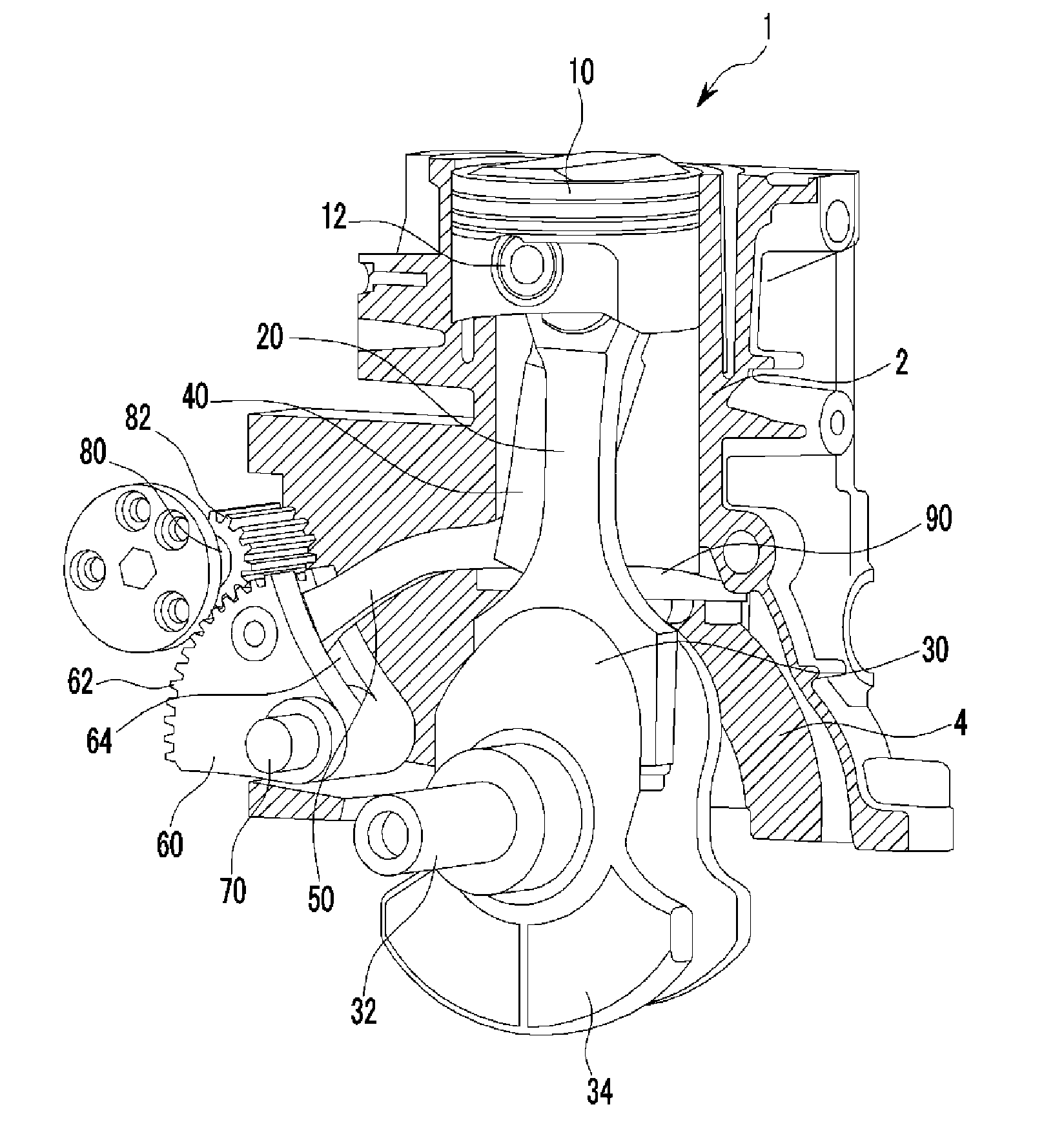
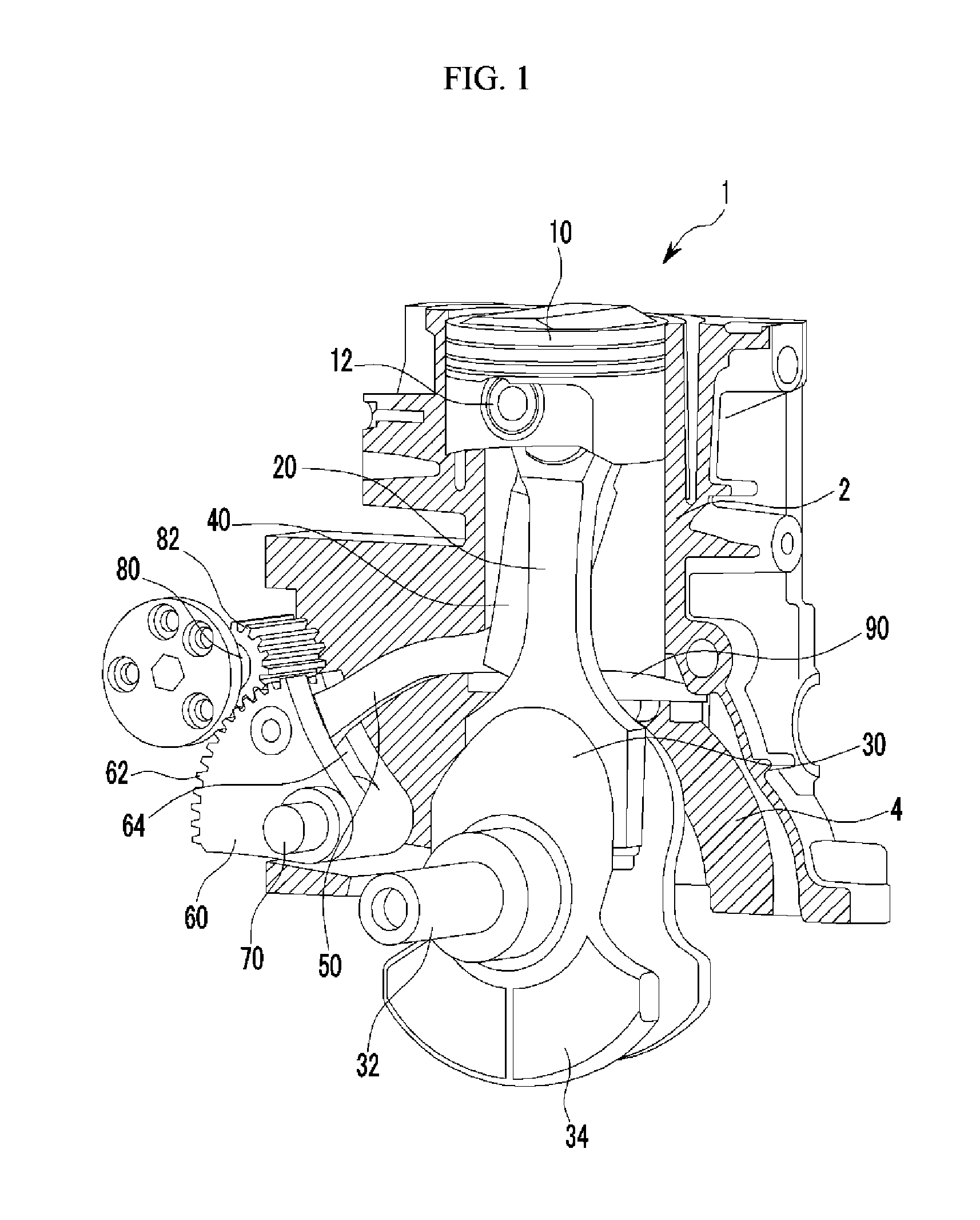
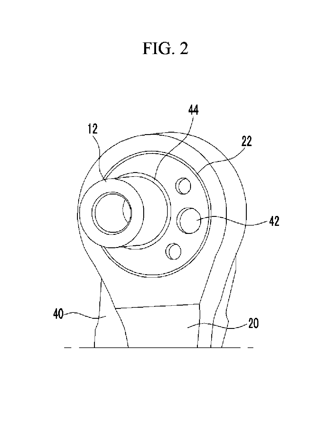
[0039]As shown in FIG. 1 to FIG. 3, a variable compression ratio apparatus 1 according to various embodiments of the present invention is mounted at an engine which receives combustion force of an air-fuel mixture from a piston 10 and rotates a crankshaft 30. The variable compression ratio apparatus changes compression ratio of the ai...


PUM


Abstract

A variable compression ratio apparatus for an engine receiving combustion force of an air-fuel mixture from a piston and rotating a crankshaft, and for changing compression ratio of the air-fuel mixture. The apparatus may include a connecting rod including one end with a mounting hole and an other end eccentrically and rotatably connected to the crankshaft, an eccentric link including one end connected to an eccentric bearing concentrically and rotatably mounted in the mounting hole, a piston pin eccentrically and rotatably mounted in the eccentric bearing, a variable link including one end rotatably connected to an other end of the eccentric link, a variable gear link pivoting with respect to a fixed shaft and formed of first gear teeth at an exterior circumference, an external circumferential portion rotatably connected to an other end of the variable link, a control shaft including second gear teeth engaged to the first gear teeth and rotating to pivot the variable gear link, and a guide bar, together with the connecting rod, limiting horizontal movement of the eccentric link.

Description

CROSS-REFERENCE TO RELATED APPLICATION[0001]This application claims priority to and the benefit of Korean Patent Application No. 10-2010-0115240 filed Nov. 18, 2010, the entire contents of which application is incorporated herein for all purposes by this reference.BACKGROUND OF INVENTION[0002]1. Field of Invention[0003]The present invention relates to a variable compression ratio apparatus. More particularly, the present invention relates to a variable compression ratio apparatus which changes compression ratio of an air-fuel mixture in a combustion chamber according to a driving condition of an engine.[0004]2. Description of Related Art[0005]Generally, thermal efficiency of combustion engines increases as the compression ratio thereof increases, and if ignition timing is advanced to some degree, thermal efficiency of spark-ignition engines increases. However, if the ignition timing of the spark-ignition engines is advanced at a high compression ratio, abnormal combustion may occur ...

Claims


Application Information

Patent Timeline
IPC IPC(8): F02D15/02
CPCF02D15/02F02B75/044
Inventor LEE, DONG SEOKYANG, JEI CHOONYANG, CHANG HOLEE, EUN HOWOO, YOONSIKKONG, JIN KOOKWOO, SOO HYUNG
Owner HYUNDAI MOTOR CO LTD
Learn More