Apparatus and method for controlling a vehicle camera
a technology for vehicle cameras and apparatus, applied in the direction of color television, television systems, transportation and packaging, etc., can solve the problems of difficult to accurately perceive the information of the preceding vehicle, economic disadvantage, and often chance of vehicle heigh
- Summary
- Abstract
- Description
- Claims
- Application Information
AI Technical Summary
Benefits of technology
Problems solved by technology
Method used
Image
Examples
first embodiment
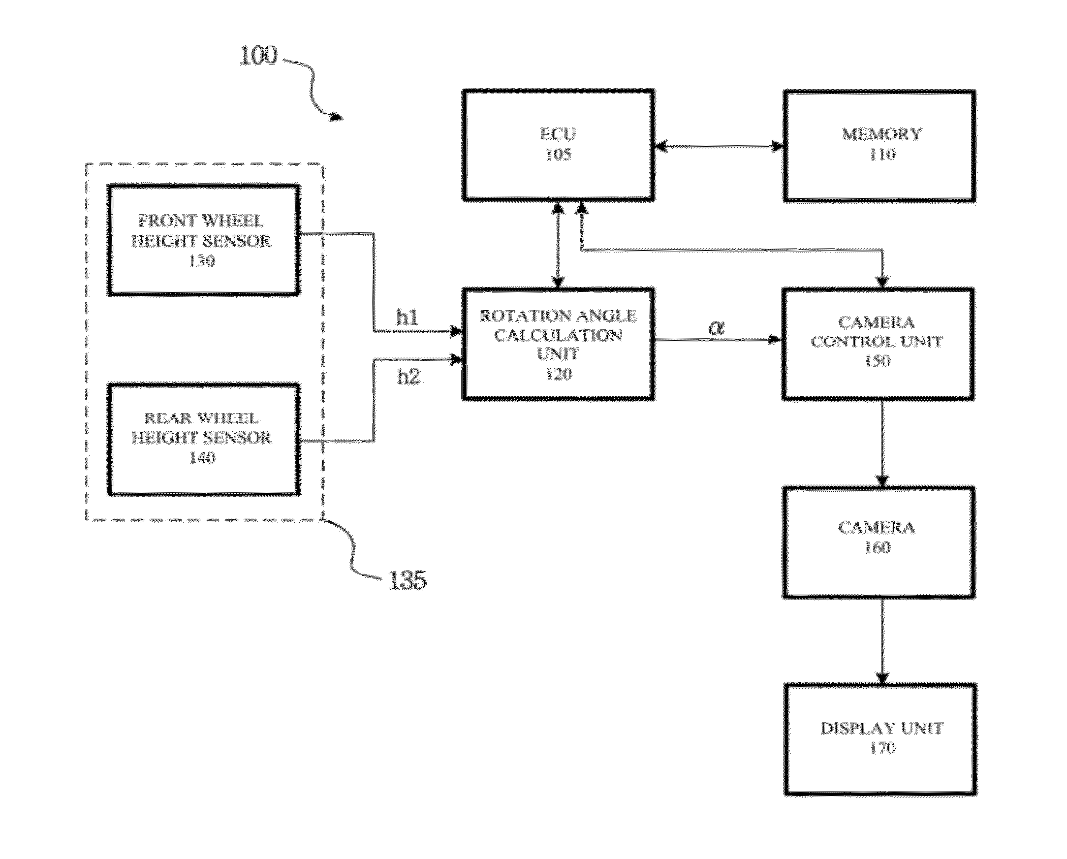
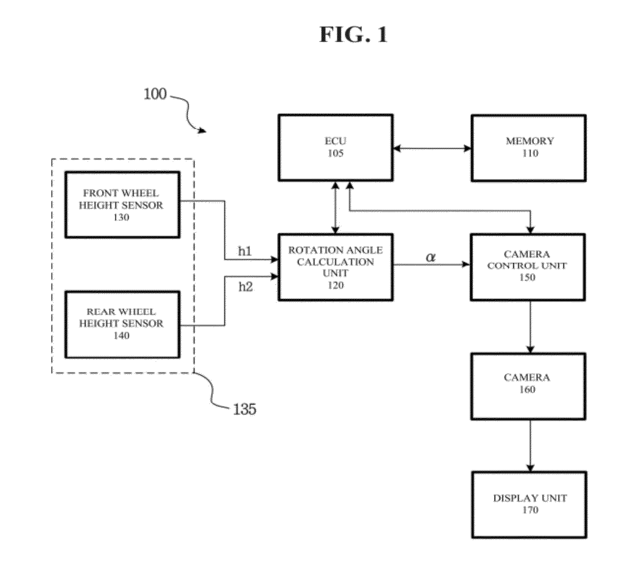
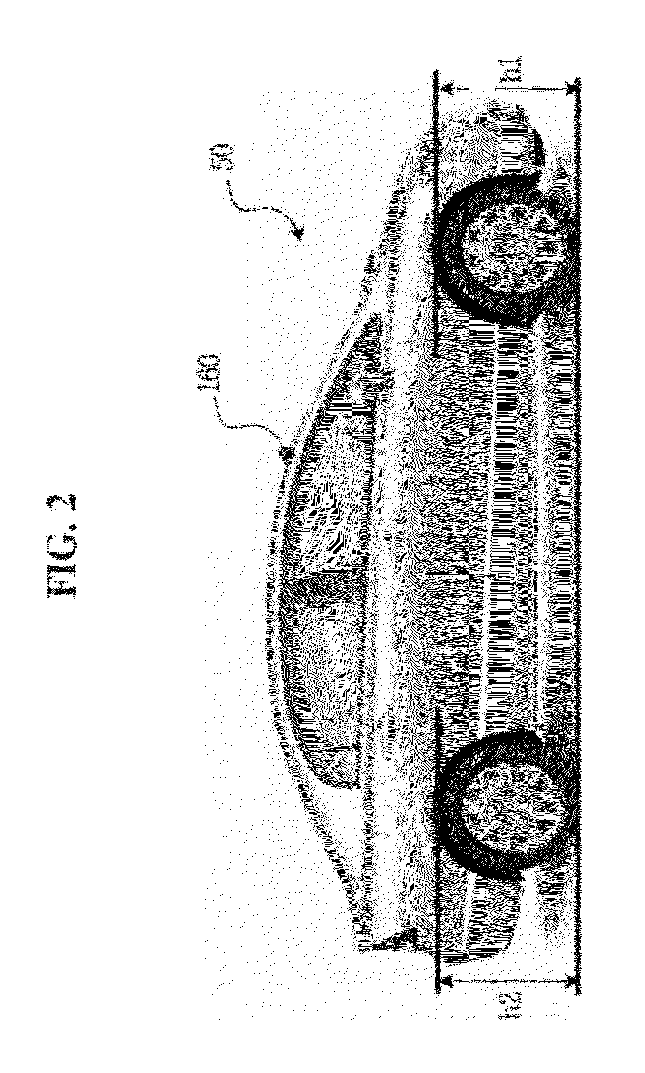
[0040]In a first embodiment, in case of detecting variation in at least one of the first vehicle height and the second vehicle height, the rotational angle calculation unit 120 computes a rotational angle of the vehicle from a distance between the position of front wheels and the position of rear wheels and an offset determined by combination of the first vehicle height and the second vehicle height, and then calculates a rotational angle compensating the computed rotational angle.
[0041]In a second embodiment, the rotational angle calculation unit 120 calculates the rotational angle based on a mapping table defining a relationship between the first vehicle height, the second vehicle height and the rotational angle. The mapping table may be stored in the memory 110. The operation of calculating the rotational angle according to the first and second embodiments will be described in detail with reference to FIGS. 3 to 12.
[0042]The camera control unit 150 controls the image pickup angle...
second embodiment
[0052]FIGS. 10 to 12 illustrate a method for creating the mapping table in accordance with the present invention.
[0053]Referring to FIG. 10, a plurality of horizontal lines s1, s2, s3, s4, etc., are arranged at equal intervals indicated on a virtual road surface. The center of an image 60 captured by the camera 160 of the vehicle is indicated by fin a state where both variations dh1 and dh2 of the initial vehicle heights h1 and h2 are zero. The position of the center f of the image 60 may be simply measured by identifying the plurality of horizontal lines.
[0054]Then, as shown in FIG. 11, if the variation dh1 of the vehicle height h1 is +a and the vehicle height h2 is fixed, a newly captured image 70 has a changed center f′. Finally, as shown in FIG. 12, in the state where the variation dh1 of the vehicle height h1 is +a, the direction of the camera 160 is controlled downward so that the captured image 60 has the original center f. In this case, if a rotational angle c of the camera ...
third embodiment
[0055]In the above-described embodiments, when an area captured by the camera is changed due to variation in height of the vehicle, it is possible to capture a fixed area in the camera by controlling the direction of the camera. However, in another embodiment (third embodiment), although a variation in height of the vehicle occurs, the same effect may be provided to a driver (i.e., the driver often does not notice the variation in height of the vehicle) by appropriately processing and displaying the captured image while the camera is in a fixed state.
[0056]FIGS. 13 to 16 illustrate operational principles in accordance with the third embodiment of the present invention. Among these, FIG. 13 shows a case where there is no change in height of the vehicle.
[0057]First, in a state where there is no change in height of the vehicle, the image 70 captured by the camera may be different from a sample image 72 actually displayed in the display unit of the vehicle. That is, only the sample imag...
PUM
 Abstract
Description
Claims
Application Information
 - R&D
- Intellectual Property
- Life Sciences
- Materials
- Tech Scout
- Unparalleled Data Quality
- Higher Quality Content
- 60% Fewer Hallucinations
Browse by: Latest US Patents, China's latest patents, Technical Efficacy Thesaurus, Application Domain, Technology Topic, Popular Technical Reports.
© 2025 PatSnap. All rights reserved.Legal|Privacy policy|Modern Slavery Act Transparency Statement|Sitemap|About US| Contact US: help@patsnap.com


