Methods, apparatus, and computer-program products for increasing accuracy in cone-beam computed tomography

a computed tomography and cone beam technology, applied in the field of methods, apparatuses and computer program products for increasing the accuracy of cone beam computed tomography, can solve the problems of non-ideal effects, non-perfect rotational symmetry about the projection axis, and spatial errors in the pixel data generated by the two-dimensional imager, so as to reduce the major source of image accuracy, reduce scattering, and improve the accuracy of the image generated from cbct.

Active Publication Date: 2011-08-30
VARIAN MEDICAL SYSTEMS
View PDF14 Cites 24 Cited by
  • Summary
  • Abstract
  • Description
  • Claims
  • Application Information

AI Technical Summary

Benefits of technology

[0005]As part of making his inventions, the inventor has recognized that, while radiologists and physicians use CBCT imaging to obtain broad images of a patient's torso during the initial portion of the diagnostic phase, they often focus their attention to specific areas of the images, such as to parts of specific organs, during the latter portion of the diagnostic phase and / or treatment phase. As also part of making his inventions, the inventor has discovered that the accuracy of the images generated from CBCT can be greatly improved by obscuring portions of the radiation source so that the radiation only passes through the specific areas of the patient related to the regions-of-interest to the doctor. The obscuring action causes less radiation to pass through the patient's body, which in turn causes the radiation to undergo less scattering through the patient's body, thus reducing a major source of error in the image accuracy. The obscuring action may be performed with bodies of material that absorb at least 60 percent of the incident radiation (and up to 100 percent); total absorption of the incident radiation is not necessary although it is sometimes preferred. Thus, as used herein, the action of obscuring a portion of a radiation beam means absorbing at least 60 percent of the incident radiation, or initial value, of that portion, and up to 100 percent thereof. The obscuring action also causes the radiation to strike a smaller portion of the two-dimensional imager. The use of less than the full area of the two-dimensional imaging device is contrary to conventional wisdom and practice in the art, which teaches artisans, physicians, and radiologists to use the full extent of the two-dimensional imager. For this reason, the prior art teaches against the present invention. The obscuring action may be done along either or both of the axial and trans-axial dimensions of the imager (the axial dimension is parallel to the rotation axis of the gantry, and the trans-axial dimension is perpendicular to the axial dimension). If the obscuring action is only done along the axial dimension, then standard 3-D reconstruction methods may be used; this is often the preferred manner of obscuring the beam. If the obscuring action is done along the trans-axial dimension (also called the lateral dimension), then truncated 3-D reconstruction methods may be used to just reconstruct limited volumes of the object being imaged. In further preferred implementations of the present inventions, an estimate of the scattered radiation may be generated from the measured pixel data of selected pixels that lie outside of the illuminated area. The scatter estimate may be subtracted from, or otherwise factored out of, the CT data set to further improve the accuracy of the data.
[0012]The obscuring of the cone beam according to the present invention reduces the field of view of the image, but improves image accuracy in the field of view. A reconstructed three-dimensional CT data set models the radiation attenuation coefficient of the object's material at a three dimensional array of locations, called voxels (which is shorthand for “volume pixels”). As a ray of radiation passes through the voxels of the object, its intensity decreases exponentially along the beam path. It is the small differences in the attenuation coefficients of the voxels that produce the subtle contrasts that physicians and radiologists use to image, identify, and diagnose problems. When there is a lot of scattering of the radiation rays, there is a lot of noise in the projection data, and this noise decreases the accuracy of reconstructing, and thereby measuring, each voxel's attenuation coefficient. The scattered radiation represents noise because it has been generated at unknown points in the object being imaged, and has been attenuated by unknown materials along unknown paths through the object. As part of making his invention, the inventor has recognized that scattered radiation generated at a point of the object can be dispersed over a wide area of the pixel array. The present invention reduces the overall magnitude of the scattered radiation by decreasing radiation in areas where it is not needed for the physicians and radiologists to see the subtle contrasts that they seek to examine. The improvement in the imaging quality results in more accurate Hounsfield units for the voxels. A Hounsfield unit is essentially a resealing of the attenuation coefficient of a voxel, where a Hounsfield unit value of 0 represents the attenuation coefficient of water, and a Hounsfield unit value of −1000 represents the attenuation coefficient of air. Voxels that are more dense than water have Hounsfield units that are greater than zero, and materials that are less dense than water have Hounsfield units that are less than zero. The Hounsfield unit system provides physicians and radiologists with higher contrast perspective to see finer details since the human body is mostly water. The present inventions improve the accuracy of measured Hounsfield units by reducing radiation scattering and reducing the field of view.

Problems solved by technology
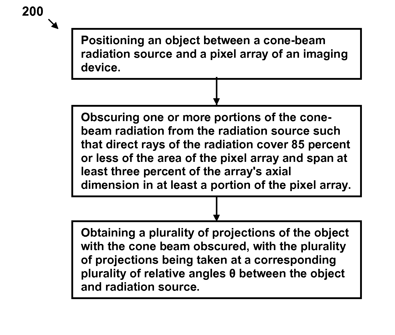
However, the shape of the radiation boundary on the imager may be non-uniform, from a large number of perturbations, so that there is no perfect rotational symmetry about the projection axis.
These scattered rays are often received by “surrounding” pixel detectors that are not located on the transmission path that the initial photon-containing-rays of radiation was transmitted on, thereby creating errors in the electrical signals of the surrounding pixel detectors.
Each of the above non-ideal effects creates spatial errors in the pixel data generated by the two-dimensional imager.
In turn, the spatial errors cause artifacts (e.g., phantom images) and loss of resolution and contrast and blurring in the CBCT image slices produced by the radiation imaging system.

Method used


Image

  • Methods, apparatus, and computer-program products for increasing accuracy in cone-beam computed tomography
  • Methods, apparatus, and computer-program products for increasing accuracy in cone-beam computed tomography
  • Methods, apparatus, and computer-program products for increasing accuracy in cone-beam computed tomography

Examples


Embodiment Construction

[0029]The inventions of the present application will be described more fully hereinafter with reference to the accompanying drawings, in which exemplary embodiments of the inventions are shown. This inventions may, however, be embodied in different forms and should not be construed as limited to the embodiments set forth herein. Rather, these embodiments are provided so that this disclosure is thorough and complete and fully conveys the scope of the inventions to one skilled in the art. In the drawings, the relative dimensions of some elements may be exaggerated for clarity. The same reference numerals are used to denote the same elements throughout the specification. The elements may have different interrelationships and different positions for different embodiments.

[0030]The terms used herein are for illustrative purposes of the present inventions only and should not be construed to limit the meaning or the scope of the present inventions. As used in this specification, a singular...


PUM


Abstract

Disclosed are methods, systems, and computer-product programs for increasing accuracy in cone-beam computed tomography (CBCT) by obscuring portions of the radiation source so that the radiation only passes through the specific areas of the patient related to the regions-of-interest to the doctor. The obscuring action causes less radiation scattering to occur in the patient's body, thereby reducing a major source of error in the image accuracy caused by scattered radiation. Scattered radiation received by detector pixels that are obscured by direct-line of sight radiation may be used to estimate the scattered radiation in the un-obscured portion, which can be used to further increase the accuracy of the image.

Description

CROSS-REFERENCES TO RELATED APPLICATIONS[0001]This application claims benefit under 35 USC 119(e) of U.S. Provisional Patent Application No. 61 / 024,903, filed Jan. 30, 2008, entitled “METHODS, APPARATUS, AND COMPUTER-PROGRAM PRODUCTS FOR INCREASING ACCURACY IN CONE-BEAM COMPUTED TOMOGRAPHY,” the content of which is incorporated herein by reference in its entirety.BACKGROUND OF THE INVENTION[0002]Cone beam (CB) computed tomography (CT) involves the imaging of the internal structure of an object by collecting several projection images (“radiographic projections”) in a single scan operation (“scan”), and is widely used in the medical field to view the internal structure of selected portions of the human body as well as in the industrial and security fields to perform non-destructive inspection and to detect contraband and weapons in security screening. Typically, several two-dimensional projections (which are images) are made of the object, and a three-dimensional representation of the...

Claims


Application Information

Patent Timeline
Patent Type & Authority Patents(United States)
IPC IPC(8): A61B6/03H05G1/64G21K1/04
CPCA61B6/032A61B6/035A61B6/06A61B6/4085G21K1/043G21K1/046
Inventor PARTAIN, LARRY
Owner VARIAN MEDICAL SYSTEMS
Why Eureka
Try Eureka