Antireflection article and display device

a display device and anti-reflection technology, applied in the direction of coatings, instruments, optics, etc., can solve the problems of insufficient abrasion resistance, low mechanical strength, easy damage to fine concave-convex structures, etc., to suppress reflectance, sufficient abrasion resistance, and sufficient abrasion resistance

Active Publication Date: 2012-05-24
MITSUBISHI CHEM CORP
View PDF3 Cites 8 Cited by
  • Summary
  • Abstract
  • Description
  • Claims
  • Application Information

AI Technical Summary

Benefits of technology

[0018]An antireflection article of the present invention of which the surface where a person or an object is likely to come in contact has sufficient abrasion resistance and can suppress reflectance at a low level throughout the visible light region.
[0019]A display device of the present invention has the outermost surface of the screen side, which has sufficient abrasion resistance, and reflectance at the outermost surface of the screen side is sufficiently low throughout the visible light region.

Problems solved by technology

However, since the convex portions of the fine concave-convex structure are very small, the mechanical strength is low and the fine concave-convex structure on the surfaces of the antireflection article has insufficient abrasion resistance.
Therefore, when the antireflection article is used for a protective filter with an antireflective function in a display device, and when a person or an object touches the surface thereof, the fine concave-convex structure is easily damaged and the antireflective function deteriorates.
However, when the aspect ratio of the convex portion is low, the difference between the maximum reflectance and the minimum reflectance in the visible light range increases, that is, the reflectance has wavelength dependency, such that it is difficult to sufficiently suppress reflection of light with some wavelengths.

Method used


Image

  • Antireflection article and display device
  • Antireflection article and display device
  • Antireflection article and display device

Examples


example 1

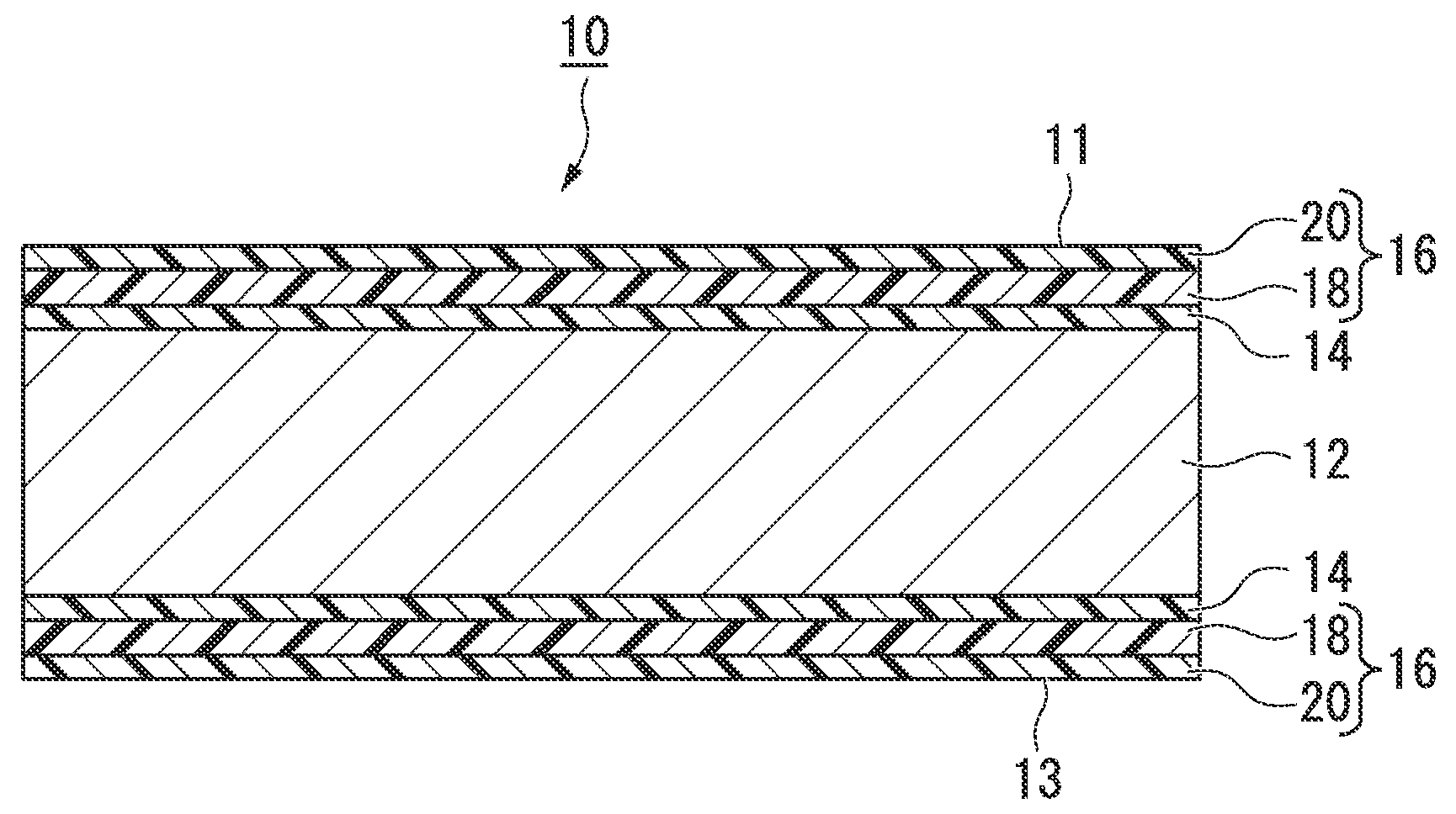
[0224]An antireflection article was acquired by bonding an antireflection film a on the front surface (first surface) of an acryl plate having a thickness of 2 mm and an antireflection film β on the rear surface (second surface), using an optical double-side bonding tape (CS0622T by Nitto Denko Corporation). A reflectance feature and abrasion resistance of the antireflection article were evaluated. The evaluation result is shown in Table 4.

example 2

[0225]An antireflection article was acquired by bonding an antireflection film α on the front surface (first surface) of an acryl plate having a thickness of 2 mm and an antireflection film γ on the rear surface (second surface), using an optical double-side bonding tape (CS0622T by Nitto Denko Corporation). A reflectance feature and an abrasion resistance of the antireflection article were evaluated. The evaluation result is shown in Table 4.

example 3

[0226]An antireflection article was acquired by bonding an antireflection film ε on the front surface (first surface) of an acryl plate having a thickness of 2 mm and an antireflection film β on the rear surface (second surface), using an optical double-side bonding tape (CS0622T by Nitto Denko Corporation). A reflectance feature and an abrasion resistance of the antireflection article were evaluated. The evaluation result is shown in Table 4.


PUM

PropertyMeasurementUnit
luminous reflectanceaaaaaaaaaa
reflectanceaaaaaaaaaa

Abstract

The present invention relates to an antireflection article of which the first surface has sufficient abrasion resistance and can suppress reflectance to a low level throughout the visible light region, and a display device. The present invention relates to an antireflection article that has light transmittance, in which a plurality of convex portions are disposed on a first surface positioned at a visible side and a second surface opposite to the first surface, the average gap of the convex portions is 400 nm or less, the ratio (H1/W1) of the height H1 of the convex portions and the width W1 of the bottoms of the convex portions is 1.3 or more, in the first surface, and the ratio (H2/W2) of the height H2 of the convex portions and the width W2 of the bottoms of the convex portions is larger than the ratio (H1/W1), in the second surface.

Description

TECHNICAL FIELD[0001]The present invention relates to an antireflection article and a display device.[0002]Priority is claimed on Japanese Patent Application No. 2009-148664, filed Jun. 23, 2009, the content of which is incorporated herein by reference.BACKGROUND ART[0003]Articles having a fine concave-convex structure with a cycle which is equal to or less than the wavelength of visible light on the surface thereof have been known to show an antireflective effect, a lotus effect, and the like. In particular, a fine concave-convex structure called a moth-eye structure has been known as effective antireflection means because a refractive index continuously increases from the refractive index of air to the refractive index of the material of the article.[0004]An article having a fine concave-convex structure on one surface or both surfaces has been proposed as an antireflection article (Patent Documents 1 and 2).[0005]However, since the convex portions of the fine concave-convex struc...

Claims


Application Information

Patent Timeline
Patent Type & Authority Applications(United States)
IPC IPC(8): G02B1/11
CPCG02B1/118
Inventor OKAMOTO, EIKO
Owner MITSUBISHI CHEM CORP
Why Eureka
Try Eureka