Vehicle securing structure

a technology for securing structures and vehicles, applied in couplings, instruments, manufacturing tools, etc., can solve the problems of adversely affecting the repeatability of tire force distribution and workload during vehicle testing, and achieve the effect of convenient inserting and repeatability of behavior

Inactive Publication Date: 2012-05-24
MEIDENSHA ELECTRIC MFG CO LTD
View PDF10 Cites 2 Cited by
  • Summary
  • Abstract
  • Description
  • Claims
  • Application Information

AI Technical Summary

Benefits of technology

[0015]The feature of the vehicle securing structure according to Claim 1 that the adapter insertion part comprises a spherical bearing, wherein the linking adapter of the vehicle securing device is inserted into the adapter insertion part, serves to obtain repeatability of behavior because the spherical bearing absorbs inclination, etc., of the vehicle.
[0016]The feature of the vehicle securing structure according to Claim 2 that the spherical bearing has a central bearing hole, wherein the bearing hole has a circular form; and the linking adapter has a circular cylindrical form, allows to easily insert the adapter into the adapter insertion part regardless of inclination, etc., of the vehicle.
[0017]The feature of the vehicle securing structure according to Claim 3 that the spherical bearing is set in a spherical bearing setting jig; and the spherical bearing setting jig is attached to a bottom surface of the vehicle, allows to secure the vehicle even if the vehicle is provided with no torque box hole on the bottom surface of the vehicle.
[0018]The feature of the vehicle securing structure according to Claim 4 that the spherical bearing setting jig comprises: a spherical-bearing-supporting member to which the spherical bearing is attached; and mounting members provided at corresponding different longitudinal end portions of the spherical-bearing-supporting member, wherein the mounting members attach the spherical-bearing-supporting member to the bottom surface of the vehicle, wherein the jig mount part such as a reinforcing beam or side sill on the bottom surface of the test vehicle is sandwiched, allows to attach the spherical bearing setting jig to the bottom surface of the vehicle.

Problems solved by technology

This causes a phenomenon that the test vehicle 101 gets restrained and released repeatedly, and thereby adversely affects repeatability of tire force distribution and workload during vehicle testing.

Method used


Image

  • Vehicle securing structure
  • Vehicle securing structure
  • Vehicle securing structure

Examples


Embodiment Construction

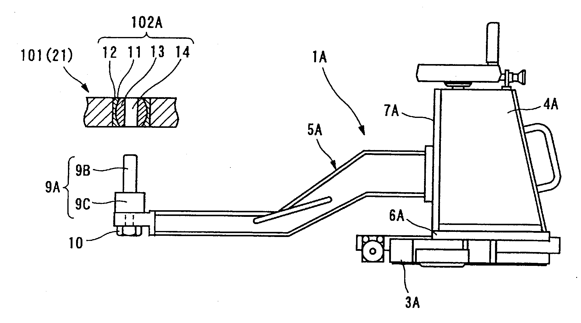
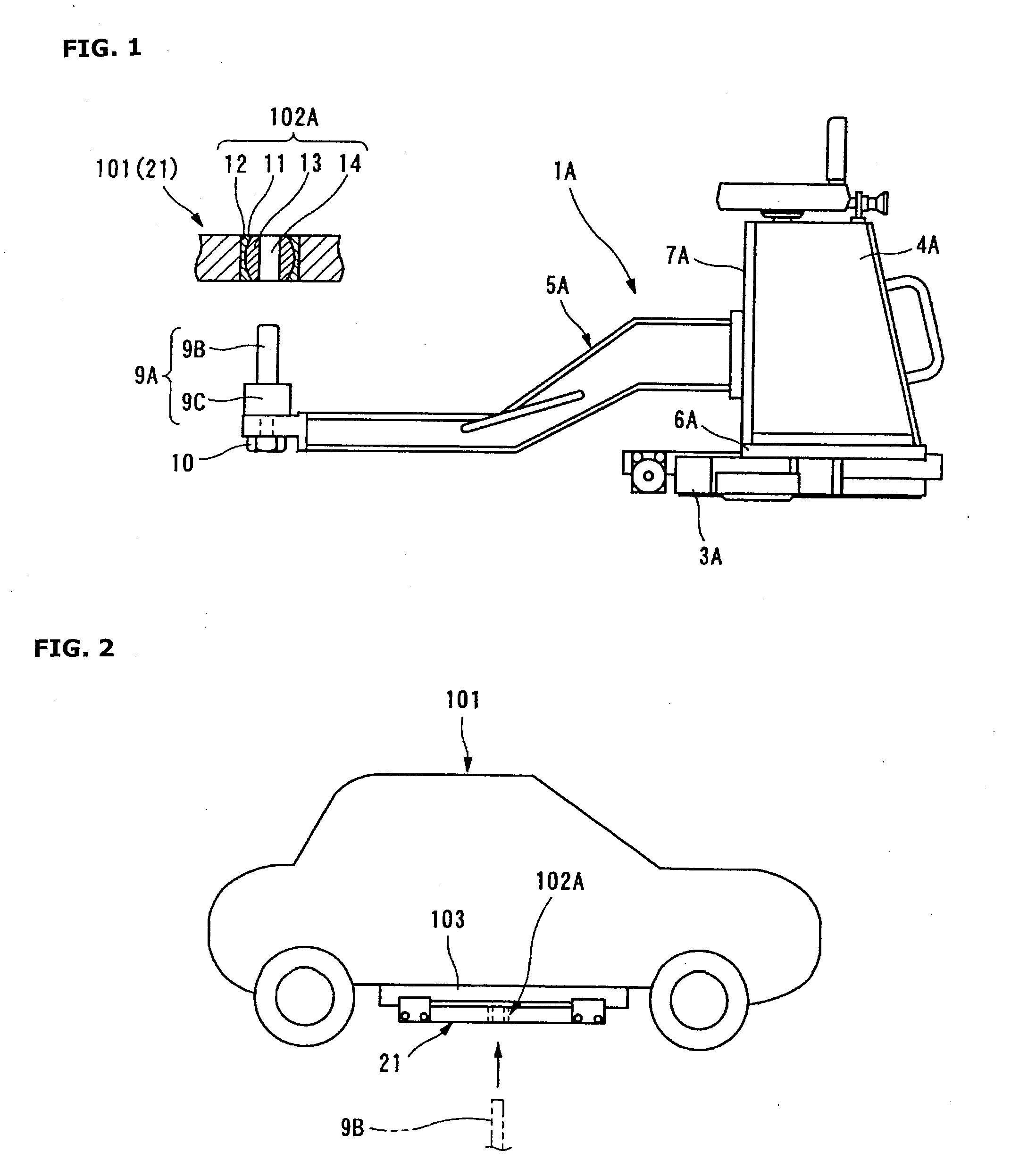
[0028]FIGS. 1 to 3 show a vehicle securing structure according to the present invention. As shown in FIG. 1, insertion of a linking adapter 9A of a vehicle securing device 1A into an adapter insertion part 102A provided in a test vehicle 101 secures the test vehicle 101.

[0029]The vehicle securing device 1A has a different outside shape from that of the vehicle securing device 1, which is described with reference to FIG. 6, but has a similar configuration as the vehicle securing device 1. The vehicle securing device 1A includes a device base part 3A, an arm support part 4A, and an arm part 5A, wherein the device base part 3A is provided in a test room and configured to slide along a rail 2A (not shown) in a longitudinal direction of the test vehicle 101, wherein the arm support part 4A is arranged on an upper surface side of the device base part 3A, and wherein the arm part 5A is cantilevered by the arm support part 4A.

[0030]The arm support part 4A is supported for sliding along a ra...


PUM


Abstract

Conventionally, the linking adapter in a vehicle securing device (1) is shaped as a square column, but this leads to problems in that the adapter insertion part is shaped as a square hole and therefore when a test vehicle tilts to the left or right during acceleration or braking in a vehicle test, the corner parts of the square-column-shaped adapter press against the inner surface of the adapter insertion part so that the test vehicle is immobilized and freed, and it is difficult to reproduce the tyre force and workload in the vehicle test. A test vehicle securing structure with which a test vehicle is secured by inserting a linking adapter (9A) in a vehicle securing device (1A) into an adapter insertion part provided in a test vehicle (101), wherein the adapter insertion part comprises a spherical bearing (102A). The adapter (9A) is formed with a cylindrical shape, while a bearing hole (14) in the spherical bearing (102A) is formed with a circular shape.

Description

TECHNICAL FIELD [0001]The present invention relates to a vehicle securing structure comprising: an adapter insertion part provided in a vehicle such as a test vehicle; and a linking adapter in a vehicle securing device, wherein insertion of the linking adapter into the adapter insertion part secures the vehicle.BACKGROUND ART [0002]There is developed one such vehicle securing device as shown in FIG. 6. The vehicle securing device 1 includes a device base part 3, an arm support part 4, and an arm part 5, wherein the device base part 3 is provided in a test room and configured to slide along a rail 2 in a direction of arrow A (in a longitudinal direction of a test vehicle 101), wherein the arm support part 4 is arranged on an upper surface side of the device base part 3, and wherein the arm part 5 is cantilevered by the arm support part 4.[0003]The arm support part 4 is supported for sliding along a rail 6 in a direction of arrow B (in a lateral direction of the test vehicle 101), whe...

Claims


Application Information

Patent Timeline
Patent Type & Authority Applications(United States)
IPC IPC(8): F16B17/00
CPCY10T403/70G01M17/0074G01M17/007
Inventor SUWAZONO, SACHIKO
Owner MEIDENSHA ELECTRIC MFG CO LTD
Why Eureka
Try Eureka