
Methods for manufacturing panels

a manufacturing method and technology of panels, applied in the field of manufacturing panels, can solve the problems of difficult to realize with these techniques in a smooth manner structures which correspond to the motif, remain partially unprotected, and realize the top layer is not really resistant to scratches or other wear

Pending Publication Date: 2021-02-25
FLOORING IND LTD
View PDF1 Cites 5 Cited by
  • Summary
  • Abstract
  • Description
  • Claims
  • Application Information

AI Technical Summary

Benefits of technology

The present invention provides techniques for forming a structure or relief on a panel without using mechanical pressure and heat. This is particularly useful for panels made of thermoplastic components and / or polyurethane, which are easily deformable when subjected to mechanical pressure and heat. The methods involve forming recesses in a second finishing layer that is free of hard particles, allowing for optimal results. The substrates can be in board form, which enhances repeatability and accuracy of the obtained structure or relief.

Problems solved by technology

So, for example, is it difficult to realize with these techniques in a smooth manner structures which correspond to the motif applied by the print.
Moreover, according to some of the known techniques the motif remains partially unprotected against, for example, wear or moisture penetration.
The known techniques show the disadvantage that the realized top layers are not really resistant against scratches or other wear.
The inventor has found that the use of sufficiently large hard particles in top layers which are structured by means of a lacquer-repelling agent, have a disadvantageous influence on the formation of the desired recesses.
Further, the maximally achievable depth and / or the depth-to-width ratio of a digital structure obtained in accordance with the prior art leaves much to be desired.

Method used


Image

  • Methods for manufacturing panels
  • Methods for manufacturing panels
  • Methods for manufacturing panels

Examples


Embodiment Construction

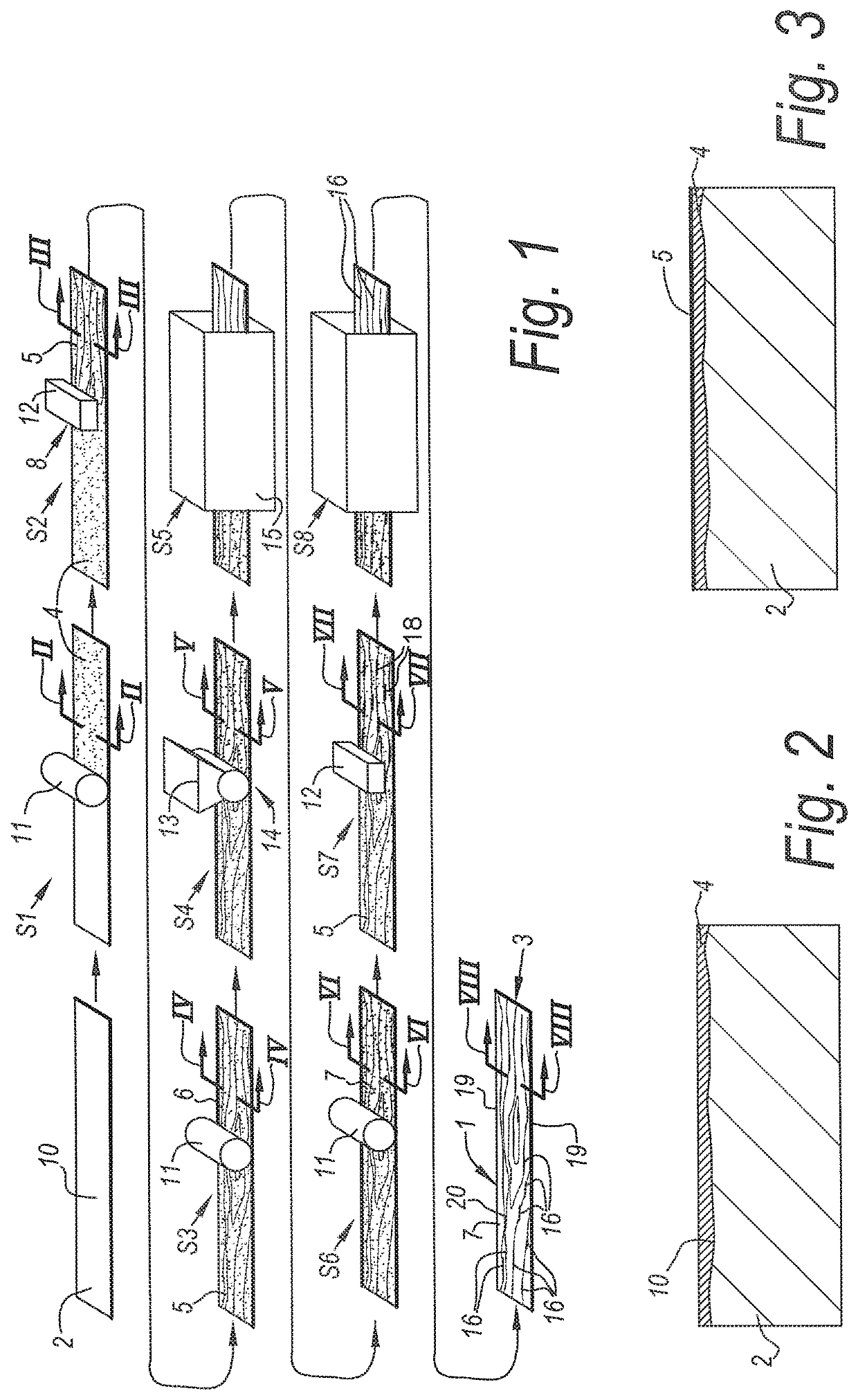
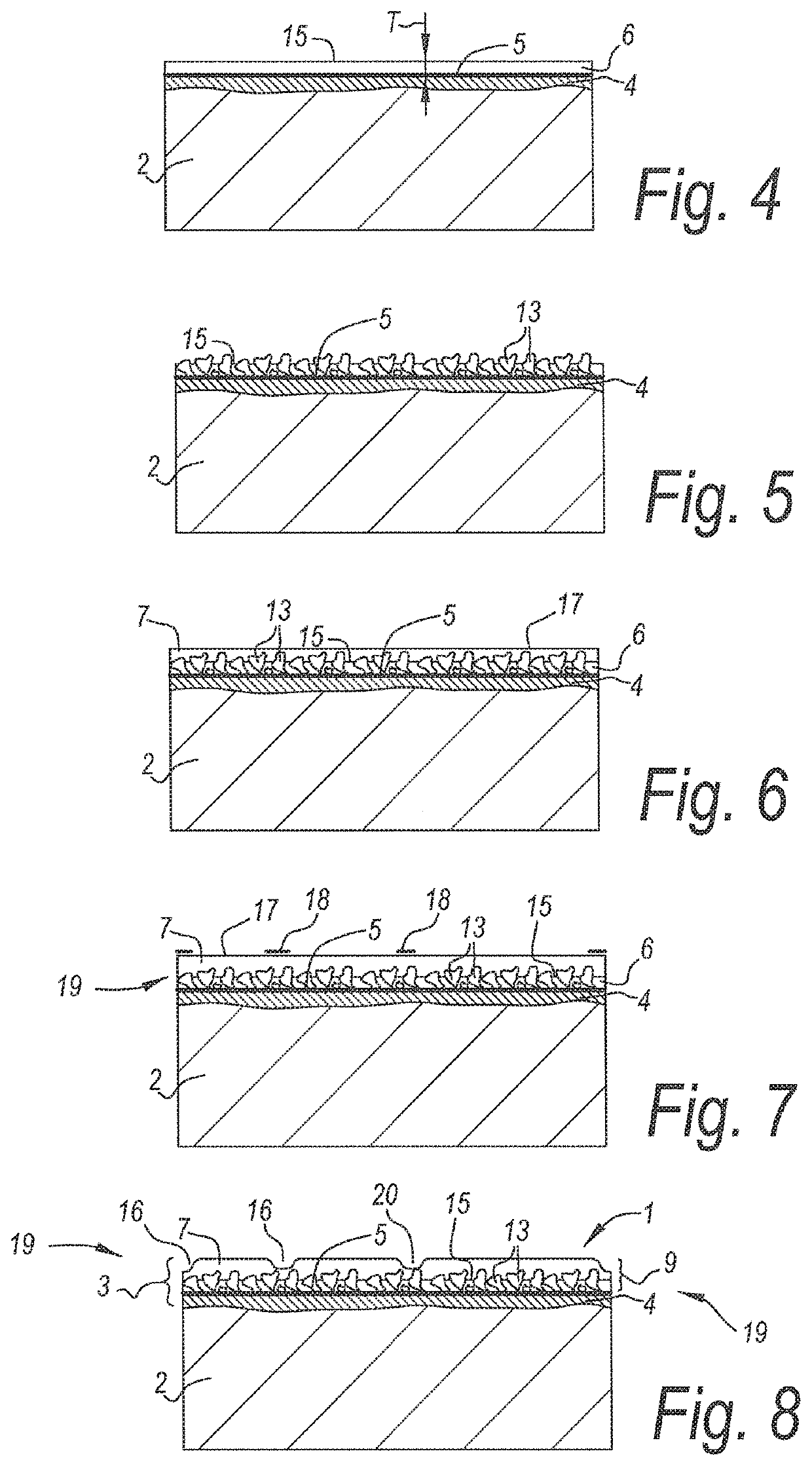
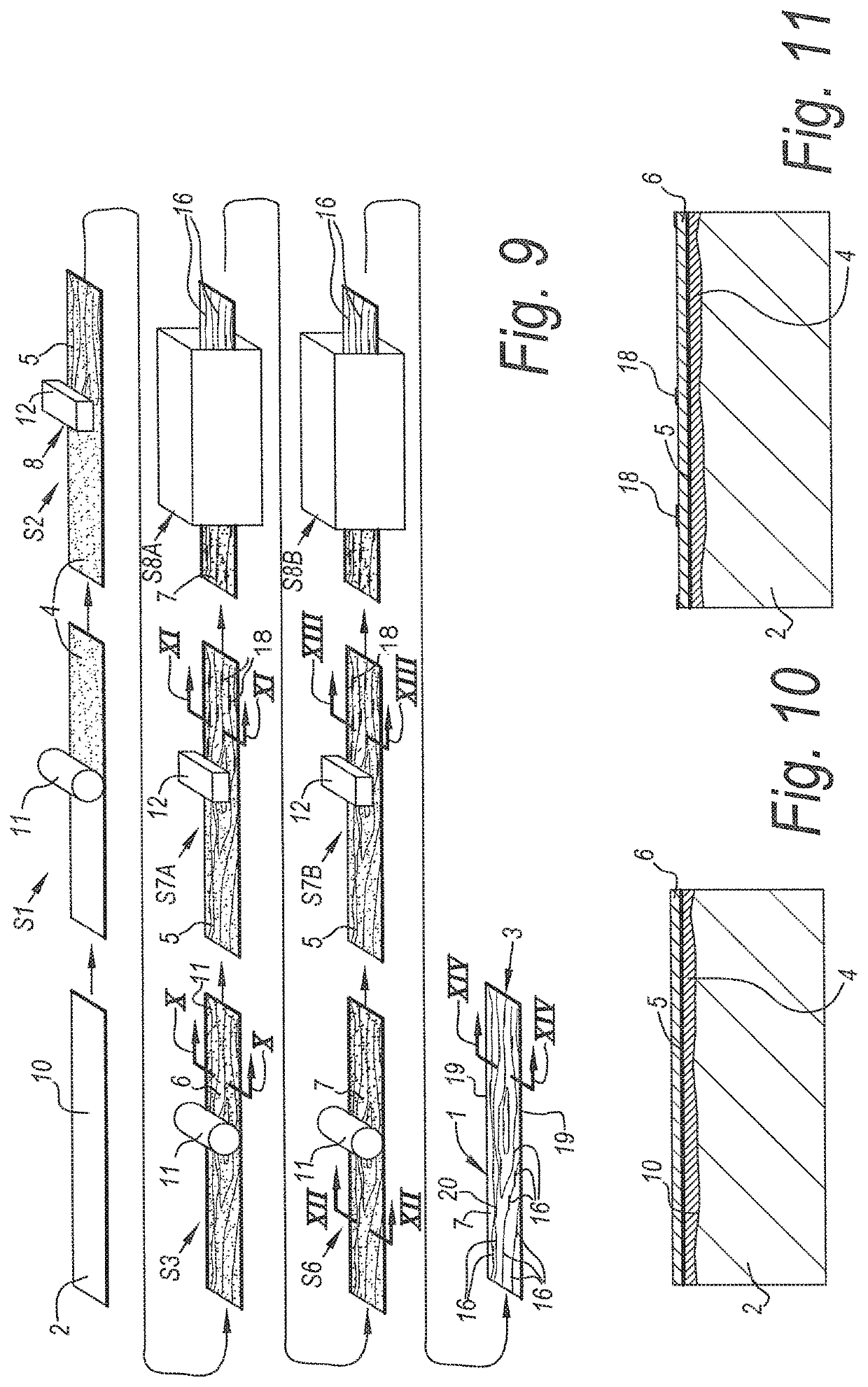
[0082]FIG. 1 schematically represents some steps S1-S8 in a method for manufacturing coated panels 1 with the characteristics of the first aspect of the invention. The respective coated panels 1 are of the type which comprises at least a substrate 2, for example, an MDF or HDF basic panel, and a decorative top layer 3 provided on this substrate 2. In the example, the top layer 3 is composed of a plurality of material layers 4-7, amongst which a material layer 5 which shows a motif and which, during step S2, is provided in the form of a print 8 realized directly on the substrate 2.

[0083]In a preceding step S1, one or more basic layers 4 are provided at the surface of the substrate 2 that has to be printed with the motif. These may have to purpose to provide an even underlying surface and / or to provide a uniform or quasi-uniform background color and / or to provide an adherent underlying surface for material layers 5-7 which have to be provided later, such as for the material layer 5 wi...


PUM

PropertyMeasurementUnit
Diameteraaaaaaaaaa
Transparencyaaaaaaaaaa
Surface tensionaaaaaaaaaa

Abstract

A method is provided for manufacturing panels with a substrate and a decorative top layer that may include a printed motif and a transparent or translucent protective layer formed there above. The method may involve applying a first and a second finishing layer for forming a first and a second portion of the protective layer. Recesses may be formed at the surface of the second finishing layer. Hard particles may be provided in the first finishing layer.

Description

[0001]This application claims priority under 35 USC § 119(a)-(d) to BE patent application No. BE2018 / 5001, which was filed on Jan. 4, 2018, the entire contents of which are incorporated herein by reference.BACKGROUND1. Field[0002]This invention relates to methods for manufacturing panels, more particularly decorative panels, such as floor panels, wall panels, ceiling panels and furniture panels.[0003]More particularly, the invention relates to methods for manufacturing panels of the type comprising at least a substrate and, provided on this substrate, a decorative top layer, for example, with a printed motif. Herein, this may relate, for example, to floor panels, furniture panels, ceiling panels, wall panels or the like, which substantially consist of an MDF or HDF (Medium or High Density Fiberboard) basic panel or substrate and a top layer provided hereon, or which are composed substantially of synthetic material, for example, with a PVC (Polyvinyl chloride)-based basic panel or su...

Claims


Application Information

Patent Timeline
IPC IPC(8): B32B37/02B32B37/10B32B37/24B32B27/14B32B27/40B32B27/30B32B27/20B44C3/00B44C5/04E04F13/08E04F15/02
CPCB32B37/02B32B37/10B32B37/24B32B27/14B32B27/40B32B27/304B32B2607/00B44C3/005B44C5/0476E04F13/0871E04F15/02B32B2037/243B32B2471/00B32B27/20B44C5/04B32B38/145B32B2419/04B32B2264/107B32B2307/554B32B2307/584B32B38/06
Inventor VERMEULEN, BRUNO
Owner FLOORING IND LTD
Learn More