Optical imaging system having an expand depth of field

an optical imaging system and expand depth of field technology, applied in the field of optical imaging systems, can solve the problems of loss of depth of field, loss of image brightness, etc., and achieve the effect of high accuracy, easy adjustment to resolution, and easy controllability

Active Publication Date: 2005-02-24
CARL ZEISS MEDITEC AG
View PDF6 Cites 16 Cited by
  • Summary
  • Abstract
  • Description
  • Claims
  • Application Information

AI Technical Summary

Benefits of technology

In another embodiment of the invention, a vaporized coating varies locally in thickness on the optical phase plate. The vaporized coating on the optical phase plate effects thereby a phase shift function. In this way, the phase shift of the optical phase plate can be determined with high accuracy by adjusting the parameters of a vaporization process.
In another embodiment of the invention, the optical phase plate is at least partially comprised of an electrostatically deformable membrane. In this way, an optical imaging system is provided wherein a wanted depth of field can be easily adapted to the resolution of a unit for generating a geometric image and, if necessary, can be electrically controlled.
In another embodiment of the invention, the optical phase plate at least partially comprises a liquid crystal display. In this way, an optical imaging system is provided wherein the phase deviation, which is caused by the optical phase plate, can be adjusted electrically and therefore is easily controllable.
In another embodiment of the invention, the optical imaging system is integrated into a microscope, especially into a surgical microscope. The depth of field, which can be achieved with such an apparatus, can therefore be greatly improved by a simple insertion of an optical phase plate in the optical beam path.
In another embodiment of the invention, the optical resolution of the optical imaging system can be adapted to the resolution capacity of the human eye. An adaptation of the optical imaging system to the resolution capacity of the human eye is understood to mean that the optical imaging system is so designed that the magnitude of the brightness distribution of an imaging object point in the image plane is not perceived by a viewer because this brightness distribution cannot be resolved by the eye. In this way, an optical imaging system is provided wherein the depth of field is increased without a discernible negative effect on the imaging quality for the viewer.
In still another embodiment of the invention, the phase plate can be pivoted into and out of the beam path. In this way, a viewer can select between a viewing image which has a very high surface sharpness and a viewing image which has a high depth of field for a surface sharpness which is constant or slightly reduced under some circumstances without this being associated with a loss of brightness.

Problems solved by technology

A shading of the geometric beam path leads, however, to a loss of image brightness.
As for a simple shading of a beam path, with the use of an apodizing mask, the increase in depth of field is, however, obtained with a loss of image brightness.
The complexity with respect to computation is then very high for high image resolution.

Method used


Image

  • Optical imaging system having an expand depth of field
  • Optical imaging system having an expand depth of field
  • Optical imaging system having an expand depth of field

Examples


Embodiment Construction

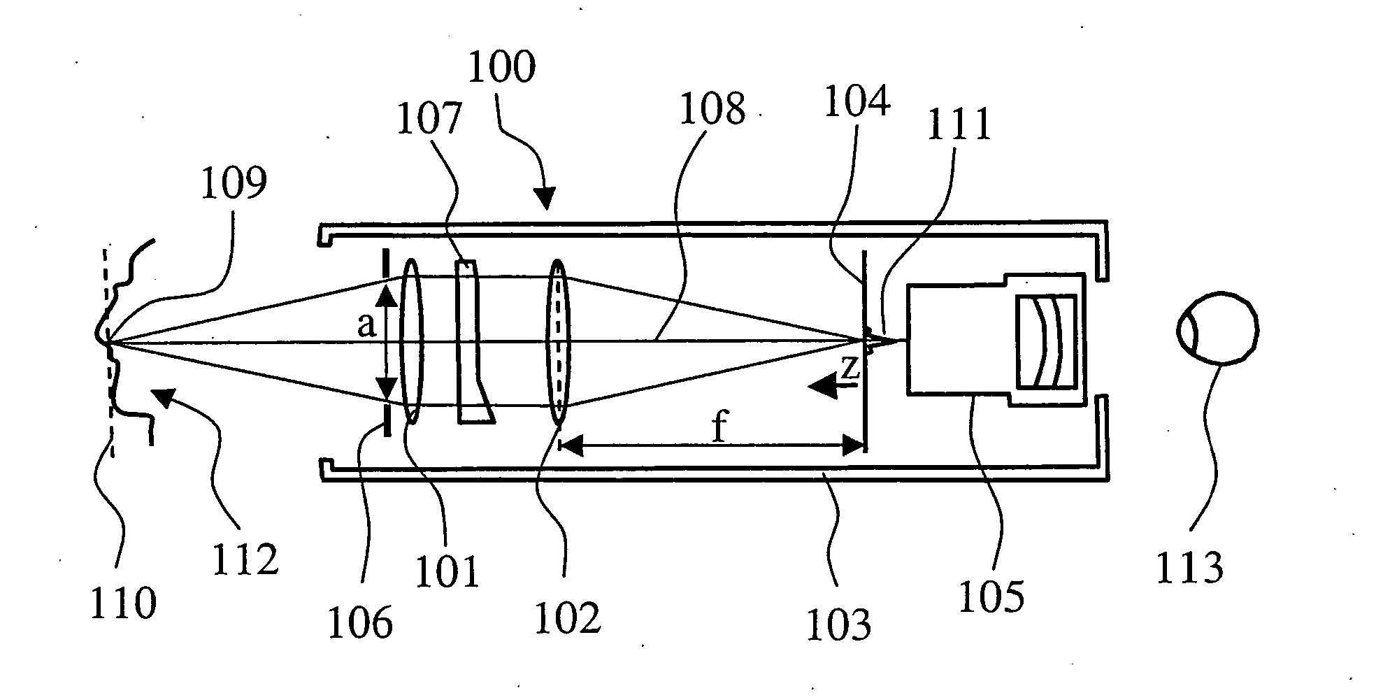
FIG. 1 shows an optical imaging system of a surgical microscope 100. The optical imaging system includes a first objective lens 101 and a second objective lens 102 which are arranged in a microscope body 103. An intermediate image is generated in an image plane 104 by means of the first objective lens and the second objective lens in the microscope body 103. This intermediate image can be viewed with an ocular unit 105. For adjusting the aperture angle for the light rays, which originate from an object region 112, a diaphragm 106 is provided in the surgical microscope 100. The diaphragm 106 determines the entry pupil of the optical system. The surgical microscope 100 has an optical phase plate 107 which is arranged in a parallel imaging beam path between the first objective lens 101 and the second objective lens 102.

This optical phase plate 107 imparts a phase offset to the light rays which pass through the phase plate. The phase offset is dependent upon the location of the pass-th...


PUM


Abstract

An optical imaging system, for example, for a surgical microscope (100) has a beam deflecting unit in order to cast light rays out of an object region (112) into an image plane (104) with an optical beam path. An optical phase plate (107) is mounted in the optical beam path. In the optical imaging system, a unit for generating a geometric image of the image plane is provided, for example, an ocular unit (105). The optical phase plate (107) is arranged on the end of the object lens (101) facing away from the object or is arranged in a region of the optical imaging system in which the beam path is parallel.

Description

CROSS REFERENCE TO RELATED APPLICATION This application claims priority of German patent application no. 103 38 472.3, filed Aug. 21, 2003, the entire content of which is incorporated herein by reference. Field of the Invention The invention relates to an optical imaging system having a beam deflection unit in order to cast light rays from an object region into an image plane. The optical imaging system further includes an optical phase plate which is mounted in the optical beam path. Background of the Invention An optical phase plate is hereinafter understood to be an optical element which is permeable to light and imparts a phase offset to a light beam passing therethrough. The phase offset is dependent upon the location of the pass-through of the light beam through the optical element. Optical imaging systems (for example, in cameras or microscopes) image an object region into an image plane via lens systems. As a rule, in such apparatus, the position of the image plane with ...

Claims


Application Information

Patent Timeline
Patent Type & Authority Applications(United States)
IPC IPC(8): G02B21/02G02B21/00G02B27/58
CPCG02B21/02G02B27/58G02B27/0075
Inventor GAIDA, GERHARDMIESNER, HANS-JOACHIM
Owner CARL ZEISS MEDITEC AG
Why Eureka
Try Eureka