
Axial gap type rotating apparatus and axial gap type generator

a technology of axial gap and rotating apparatus, which is applied in the direction of rotating magnets, electrical apparatus, synchronous machines with stationary armatures, etc., can solve the problems of reducing the magnetic flux, increasing the reluctance, and affecting the effect of increasing output, so as to increase the magnetic flux passing across the coil, increase the output, and increase the magnetic flux. the effect of the coil

Inactive Publication Date: 2012-05-31
NISCA KK
View PDF6 Cites 31 Cited by
  • Summary
  • Abstract
  • Description
  • Claims
  • Application Information

AI Technical Summary

Benefits of technology

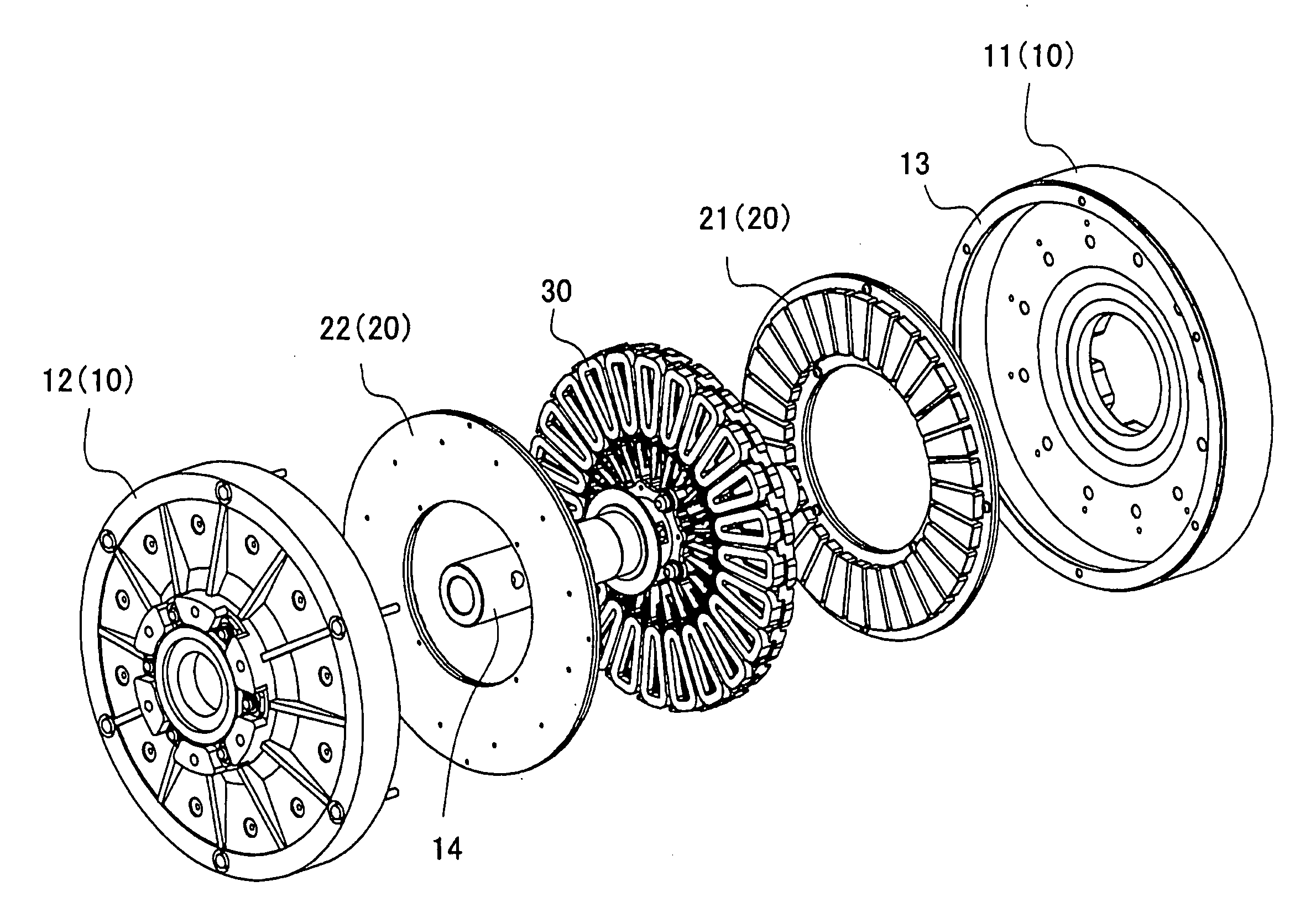
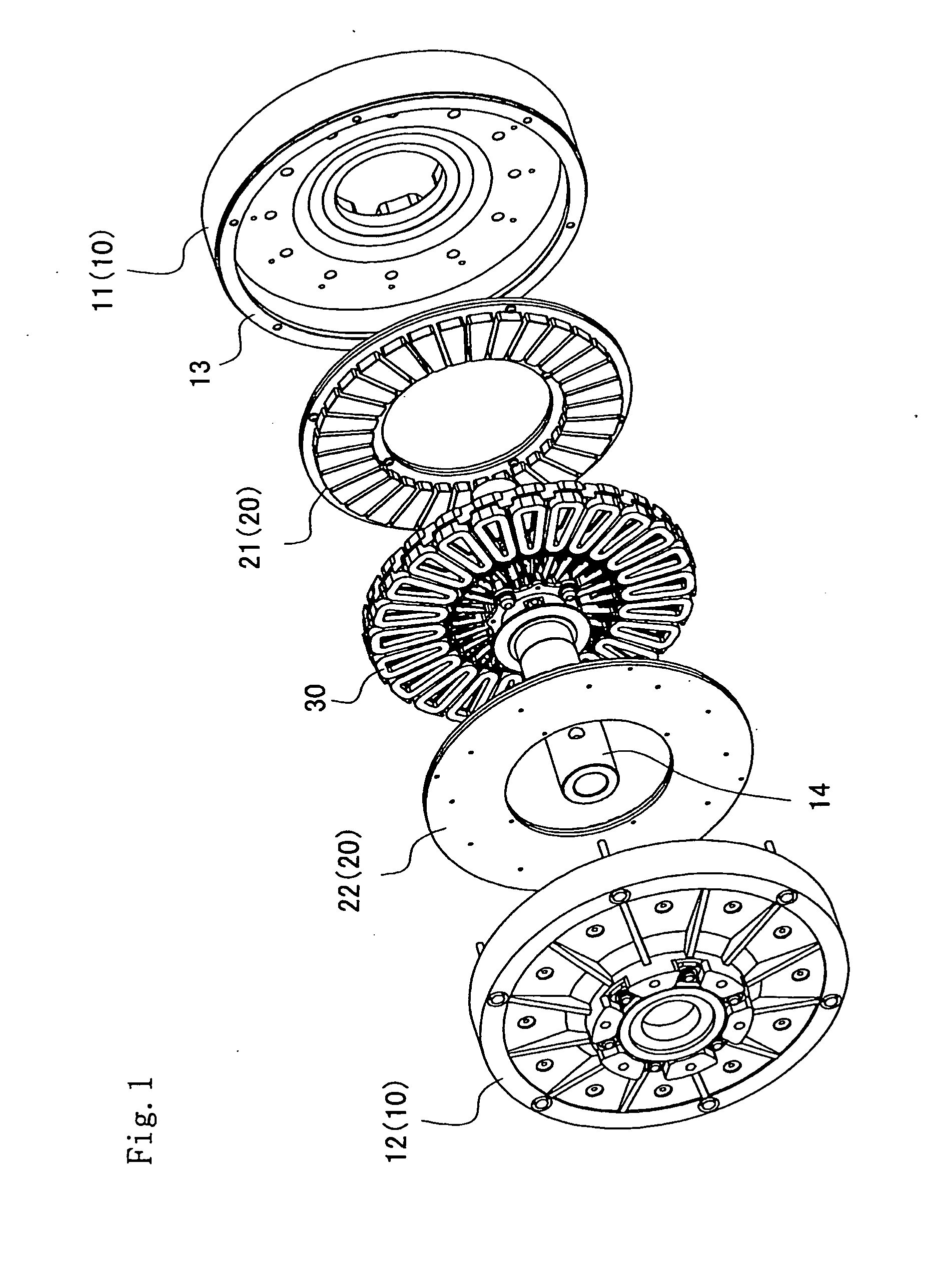
[0010]It is an object of the invention to provide an axial gap type rotating apparatus for enabling downsizing and high output by causing the magnetic field to pass across the coils effectively in arranging the magnets and coils to oppose one another in the axial direction of the rotor shaft.SUMMARY OF THE INVENTION
[0014]In the invention, pluralities of segment coils and segment magnets are arranged radially in the circumferential direction of the rotor shaft, each of the segment coils is comprised of an air-core coil, the segment yoke pieces of soft magnetic material in non-contact with the wiring are arranged in the non-winding portions in a discontinuous state while being separate for each non-winding portion, and therefore, the following effect is produced.
[0016]Thus, in the invention, the yoke piece of soft magnetic material is provided between the magnetic poles opposed to each other with the coil therebetween, and therefore, even when the gap between the magnetic poles is increased, it is possible to increase the magnetic flux passing across the coil by magnetism concentration action of the yoke piece.
[0017]Further, in the invention, pluralities of segment coils are arranged in a layered manner in the axial direction of the rotor shaft, the coil group in the layered manner is displaced by a predetermined angle in the circumferential direction of the rotor shaft, and the yoke piece arranged in the non-winding portion of each of the segment coils thereby concentrates magnetism in the direction for passing across the coils of adjacent layers. By this means, it is possible to increase the magnetic flux passing across the coils in parallel with the axial direction, and to further increase output.

Problems solved by technology

The increase in the magnet gap results in an increase in reluctance, reduces the magnetic flux, and is the detrimental effect in increasing output.
Therefore, the reluctance increases, and there has been the problem that desired output is not obtained in spite of the fact that the apparatus is increased in size by increasing the coil capacity.

Method used


Image

  • Axial gap type rotating apparatus and axial gap type generator
  • Axial gap type rotating apparatus and axial gap type generator
  • Axial gap type rotating apparatus and axial gap type generator

Examples


embodiment 1

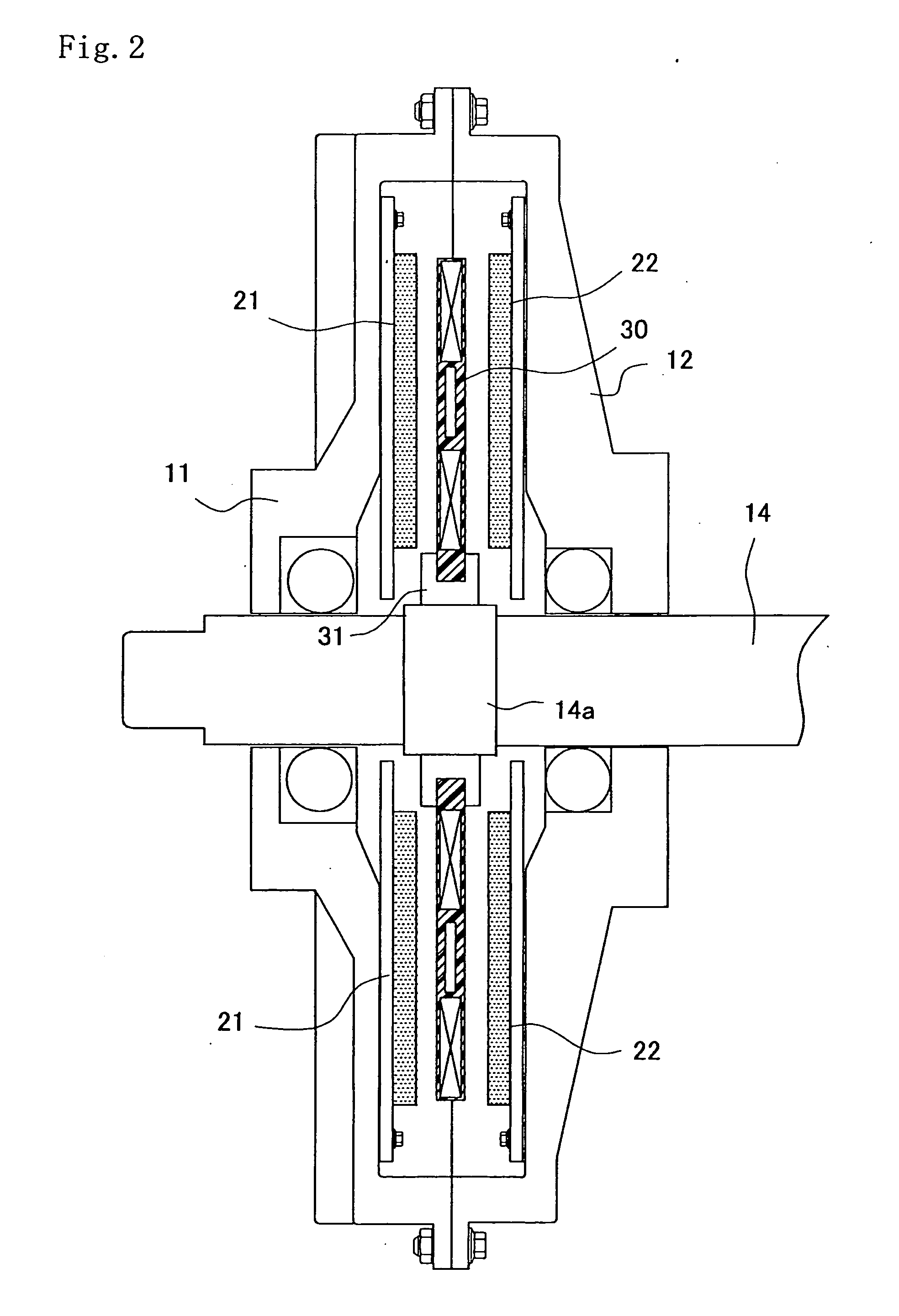
[0048]The Embodiment as shown in FIGS. 5A and 5B shows the case where the segment coils 32 are configured in one-layer structure. The pair of core yokes 21, 22 are spaced a distance d1 and located in the fixed shaft 14. In each of the core yokes 21, 22 are arranged magnet pieces 23x, 23y to form mutually opposed magnetic poles. In between the first and second core yokes 21, 22 are arranged the coil elements 32 fixed to the fixed shaft 14.

[0049]The magnet pieces 23x, 23y are spaced an air gap d1 to form opposed magnetic poles, and the coil elements 32 are disposed in the center (d1 / 2). In each of the coil elements 32, the yoke piece 33 is disposed in the non-winding portion 32Co of the core center while being in non-contact with the winding. The yoke piece 33 is spaced equal distances from the pair of core yokes (22).

[0050]As described previously, the magnet pieces 23x, 23y, coil elements 32 and yoke pieces 33 are arranged radially in the circumferential direction of the fixed shaft ...

embodiment 2

[0052]The Embodiment as shown in FIGS. 6A and 6B shows the case where the segment coils 32 are configured in two-layer structure. A first coil layer 32x and second coil layer 32y are arranged in the axial direction of the rotor shaft 14 in between the pair of core yokes 21, 22 configured as in above-mentioned Embodiment 1. The yoke piece 33x, 33y is arranged in the non-winding portion 32Co of each coil element. Then, in the first coil layer 32x and the second coil layer 32y is formed a phase difference with an offset amount δ in the rotation direction of the rotor. In other words, the first coil layer 32x and the second coil layer 32y are arranged as upper and lower layers in the axial direction of the rotor shaft, and are offset by a distance δ in the coil element of the first coil layer 32x and the coil element of the second coil layer 32y.

[0053]FIG. 6B shows the offset state, where the coil element (solid line in FIG. 6B) of the first coil layer 32x and the coil element (dashed ...

embodiment 3

[0054]The Embodiment as shown in FIGS. 7A and 7B is a modification of Embodiment 1 as shown in FIGS. 5A and 5B, and shows the case where the segment coils 32 are configured in two-layer structure as in the Embodiment in FIGS. 6A and 6B. In the Embodiment as shown in FIG. 7A, the yoke piece 33 is formed in the non-winding portion of each of the first coil layer 32x and the second coil layer 32y without any phase difference being formed. Meanwhile, in FIG. 7B, one yoke piece is disposed between the first coil layer 32x and the second coil layer 32y without any phase difference being formed. The other configuration is the same as in Embodiment 2 and is assigned the same reference numerals to omit descriptions.

[Output Property in Each Embodiment]

[0055]FIG. 8 shows the property of effective magnetic flux density of each Embodiment. In FIG. 8, the horizontal axis represents the position in the magnet, the dotted lines in the center show the center thereof, and the vertical axis represents...


PUM


Abstract

The invention is to provide an axial gap type rotating apparatus for enabling downsizing and high output by causing the magnetic field to pass across the coils effectively in arranging the magnets and coils to oppose one another in the axial direction of the rotor shaft, in which in arranging pluralities of segment magnets and segment coils radially to oppose one another in the circumferential direction of the rotor shaft, each segment coil is comprised of an air-core coil having a non-winding portion in the center, a segment yoke piece of soft magnetic material is provided in the non-winding portion while being in non-contact with the winding, and the segment yoke pieces are arranged discontinuously in a separate state for each of non-winding portions of a plurality of segment coils.

Description

BACKGROUND OF THE INVENTION AND RELATED ART STATEMENT[0001]1. Field of the Invention[0002]The present invention relates to an axial gap type rotating apparatus such as an electric motor and generator in which pluralities of magnets and segment coils are radially arranged to oppose one another in the circumferential direction of a rotation shaft (or fixed shaft) with gaps formed in the axial direction.[0003]2. Description of the Prior Art[0004]Generally, in a rotating apparatus such as a motor and generator, permanent magnets are arranged in one of the stator and the rotor, coils are arranged in the other one to oppose, and the torque or electromotive force is output by rotation of the rotor. Particularly, this type of rotating apparatus has recently been used as an apparatus to obtain driving output concurrently with power generation as hybrid driving.[0005]Conventionally, the axial gap type rotating apparatus has been known as such a rotating apparatus. The rotating apparatus is kn...

Claims


Application Information

Patent Timeline
Patent Type & Authority Applications(United States)
IPC IPC(8): H02K21/24
CPCH02K21/24H02K16/00
Inventor HAYAKAWA, YUKIHIKO
Owner NISCA KK
Learn More