Digital broadcast reception device and digital broadcast reception method
a digital broadcast and reception device technology, applied in the field of digital broadcast reception devices and digital broadcast reception methods, can solve the problems of inability to view or listen to the broadcast service provided by the physical channel, which was being received normally until then, and achieve the effect of reducing the frequency of channel scanning, improving the accuracy of automatic channel switching, and prolonging the period of program viewing or listening
- Summary
- Abstract
- Description
- Claims
- Application Information
AI Technical Summary
Benefits of technology
Problems solved by technology
Method used
Image


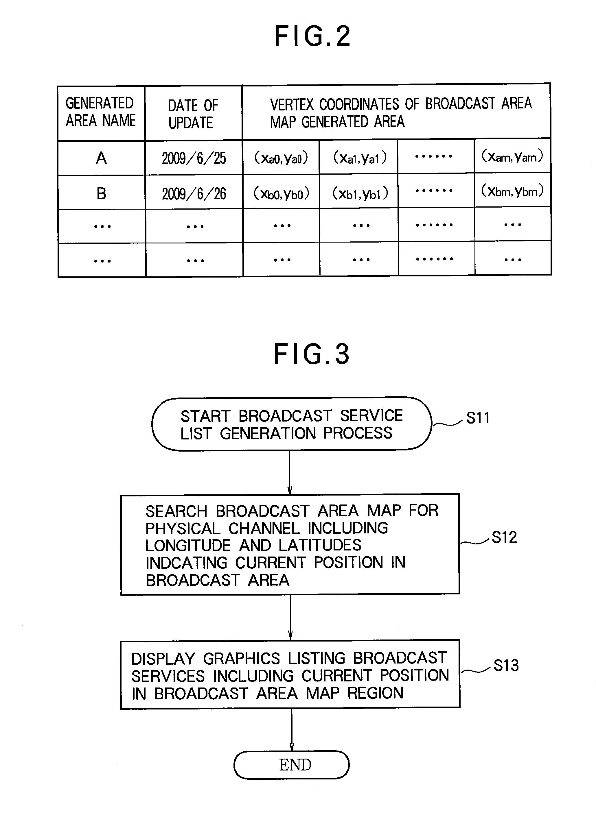
Examples
first embodiment
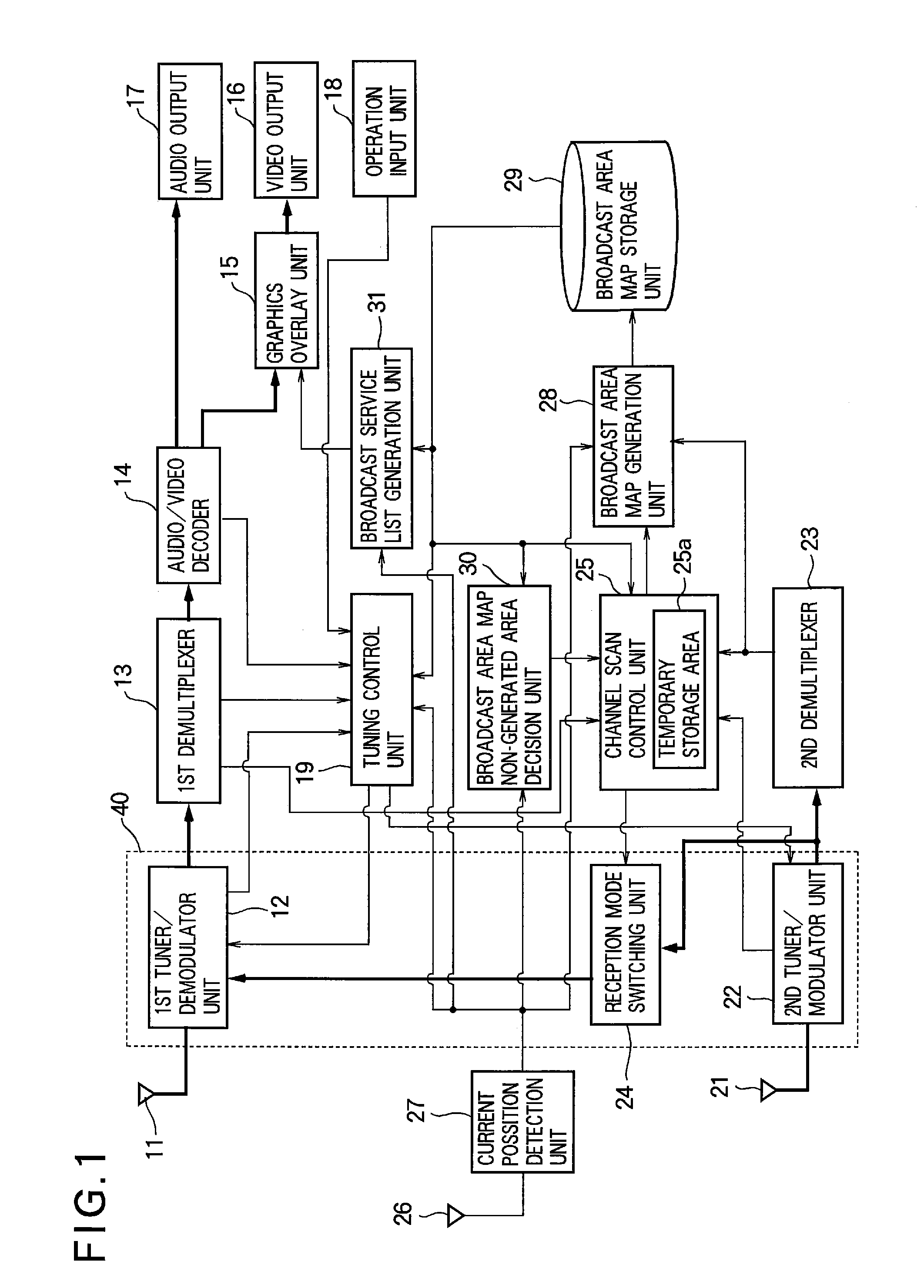
[0058]FIG. 1 is a block diagram schematically illustrating the structure of the digital broadcast reception device according to a first embodiment. As shown in FIG. 1, the digital broadcast reception device includes a first antenna 11, a first tuner / demodulator unit 12, a first demultiplexer 13, an audio / video decoder 14, a graphics overlay unit 15, a video output unit 16, an audio output unit 17, an operation input unit 18, and a tuning control unit 19. The digital broadcast reception device according to the first embodiment also includes a second antenna 21, a second tuner / demodulator unit 22, a second demultiplexer 23, a reception mode switching unit 24, a channel scan control unit 25, an antenna (e.g., a GPS antenna) 26 for use in detecting the current position, a current position detection unit 27 that detects the current position from a signal from antenna 26, a broadcast area map generation unit 28, broadcast area map storage unit 29, a broadcast area map non-generated area d...
second embodiment
[0091]FIG. 10 is a drawing showing an exemplary broadcast area map stored in the digital broadcast reception device according to the second embodiment; FIG. 11 is a drawing illustrating, in tabular form, the structure of the broadcast area map stored in the digital broadcast reception device according to the second embodiment. The difference from the first embodiment is that a non-receivable area (the white area in the shaded area) is added inside the receivable area (shaded area) of the broadcast area map generated by the digital broadcast reception device according to the first embodiment. The description of the second embodiment will also refer to FIG. 1.
[0092]In FIG. 10, an example of the receivable area 60 of a broadcast service being transmitted by a certain broadcast station A1 with TS name or an ensemble name ‘oooo’ is shown; in FIG. 11, the receivable area of each broadcasting station is shown in tabular form. FIGS. 10 and 11 depict a case in which the receivable area 60 in...
third embodiment
[0095]FIG. 12 is a drawing showing an exemplary broadcast area map stored in the digital broadcast reception device according to the third embodiment; FIG. 13 is a drawing illustrating the structure of the broadcast area maps stored in the digital broadcast reception device according to the third embodiment. The structure of the broadcast area maps in the digital broadcast reception device according to the third embodiment differs from the structure of the broadcast area maps generated by the digital broadcast reception device according to the first embodiment. The description of the third embodiment will also refer to FIG. 1.
[0096]In FIG. 12, an example of a receivable area 70 of the broadcast service being transmitted by a certain broadcast station A1 with the TS name or ensemble name ‘oooo’ is shown; in FIG. 13, the receivable area of each broadcasting station is shown in tabular form. The digital broadcast reception device according to the third embodiment is the same as in the ...
PUM
 Abstract
Description
Claims
Application Information
 - R&D
- Intellectual Property
- Life Sciences
- Materials
- Tech Scout
- Unparalleled Data Quality
- Higher Quality Content
- 60% Fewer Hallucinations
Browse by: Latest US Patents, China's latest patents, Technical Efficacy Thesaurus, Application Domain, Technology Topic, Popular Technical Reports.
© 2025 PatSnap. All rights reserved.Legal|Privacy policy|Modern Slavery Act Transparency Statement|Sitemap|About US| Contact US: help@patsnap.com