Volute and drainage pump

a technology which is applied in the field of valve and drainage pump, can solve the problems of increasing the noise created by the valve and producing irritating noises of varying frequency or pitch, and achieves the effect of improving sound quality and being easy to accep

Active Publication Date: 2012-05-31
JOHNSON ELECTRIC SA
View PDF14 Cites 3 Cited by
  • Summary
  • Abstract
  • Description
  • Claims
  • Application Information

AI Technical Summary

Benefits of technology

[0005]The present invention aims to provide a new volute and a new drainage pump using same which can solve, or at least reduce, the above mentioned problem. This is achieved by providing the volute with an inner surface which is purposely not smooth so as to create a turbulent mixing of the air and water during the air / water phase which is thought to produce an air / water mixture in which the air is predominately in small bubbles thereby generating a noise of a substantially constant range of frequencies or pitch from the pump. This is commonly referred to as improving the quality of the noise produced by the pump.

Problems solved by technology

During the air / water phase, air is sucked into the drainage pump, producing an increase in the noise created by the pump.
It is thought that these air pockets are responsible for producing an irritating noise of varying frequency or pitch which is emitted by the drainage pump during the air water phase.

Method used


Image

  • Volute and drainage pump
  • Volute and drainage pump
  • Volute and drainage pump

Examples


first embodiment

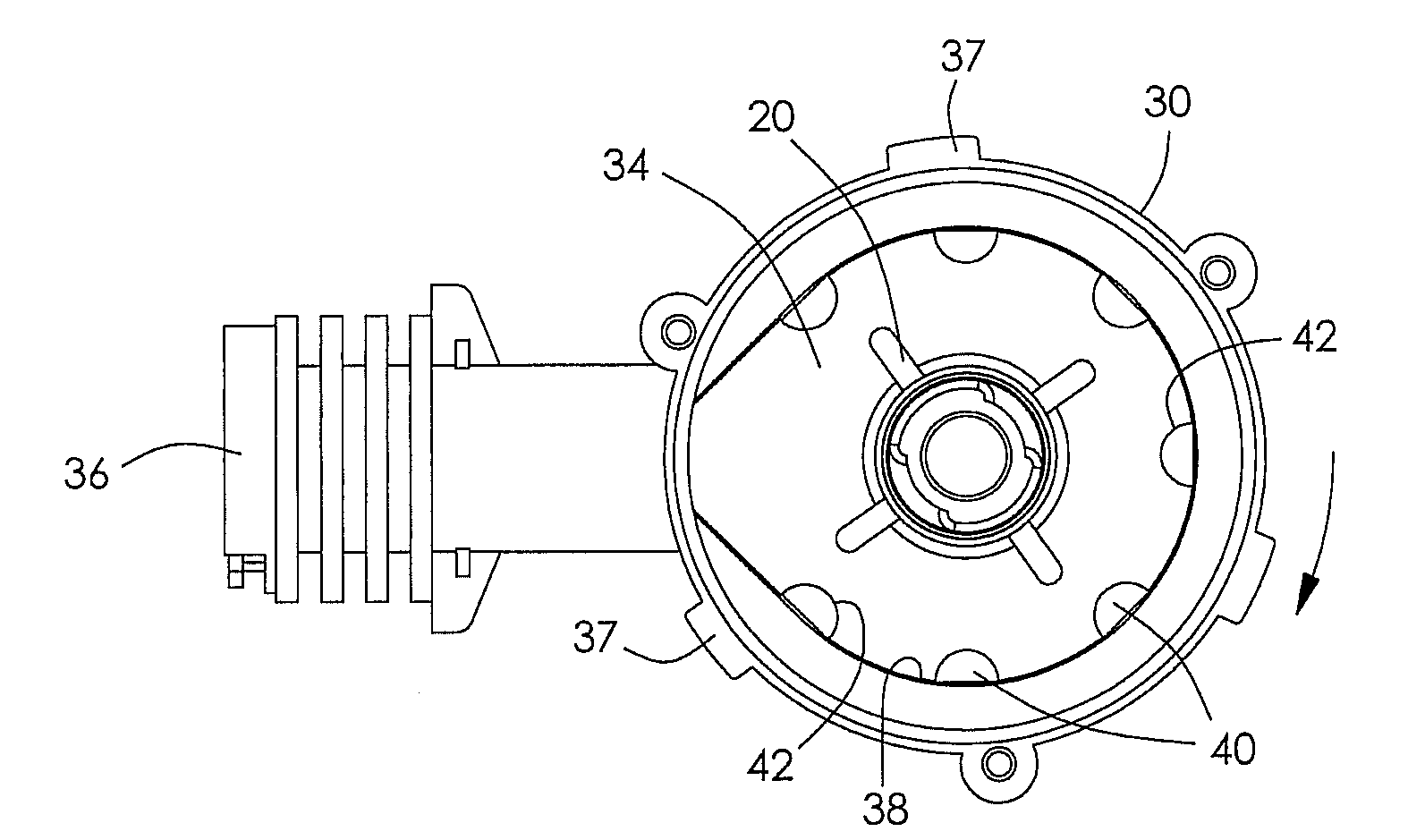
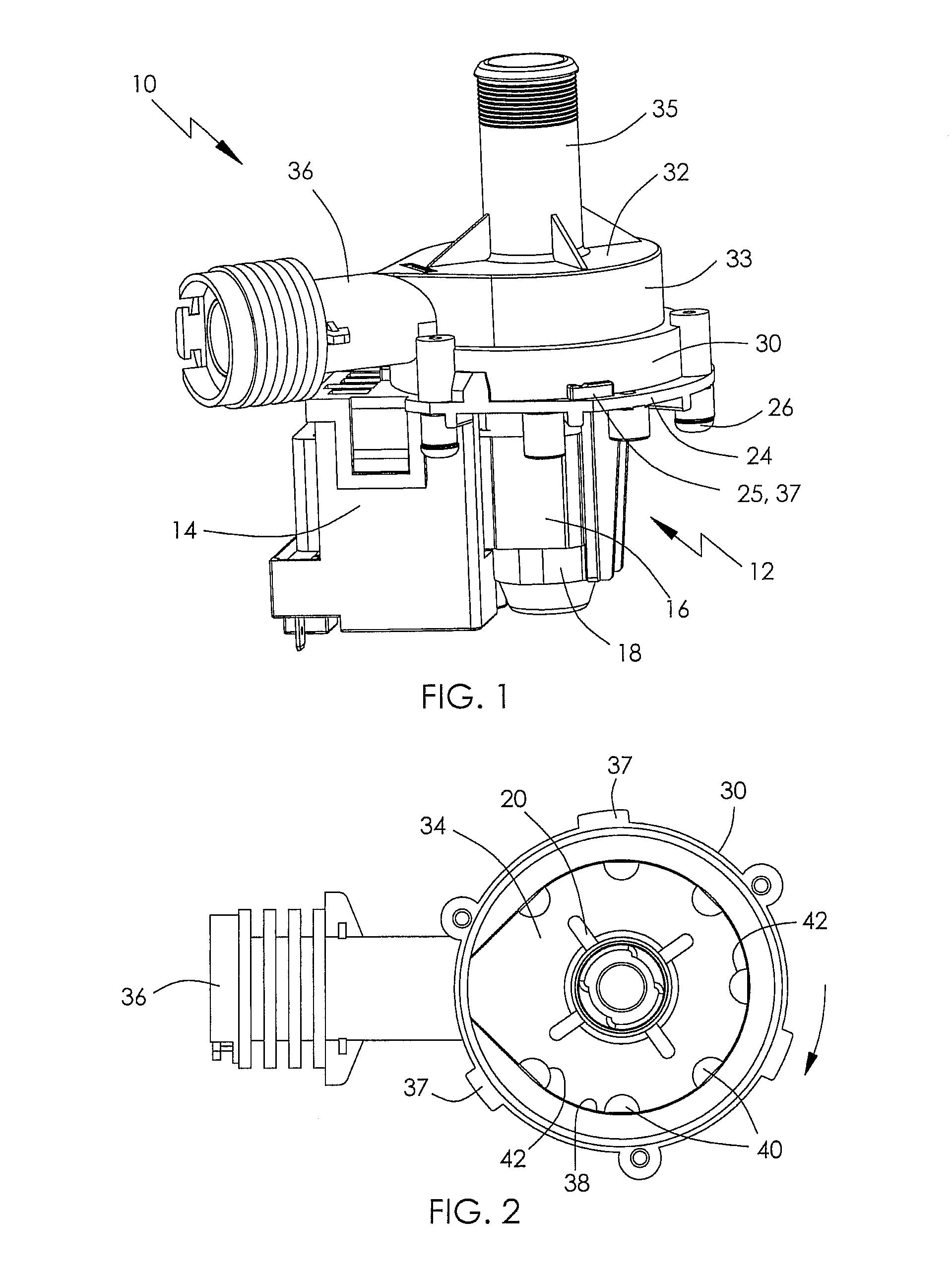
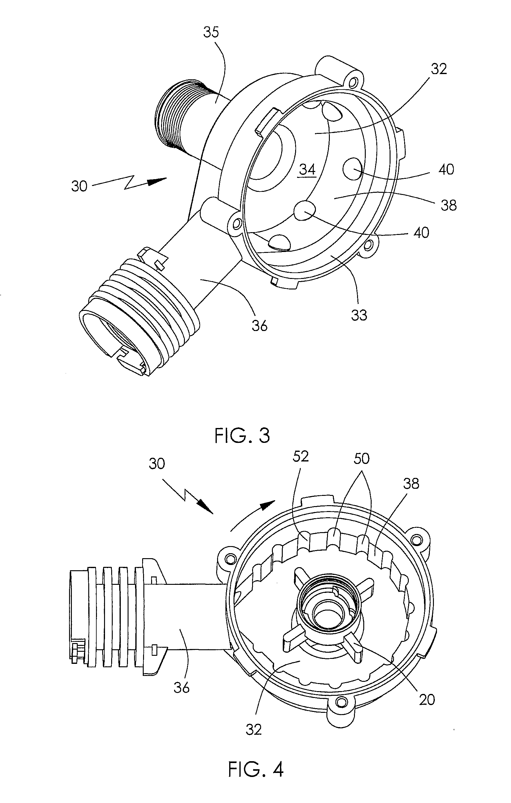
[0030]Referring especially to FIG. 2, in the present invention, the volute 30 includes a number of protrusions 40 protruding inwardly from the inner surface 38. The protrusions 40 may be integrally formed with the side wall 33. Each protrusion 40 is substantially hemispheric or at least partly spherical, and the surface thereof constitutes the interfering surface 42. The interfering surface 42 faces substantially to the flow direction (shown by the arrow) of the fluid in the pump chamber 34. The protrusions 40 are preferably arranged at regular angular intervals along the circumferential direction of the inner surface 38. As shown in FIG. 3, the protrusions 40 are preferably centered in different planes spaced in the direction of the motor axis. Optionally, the protrusions are alternately centered on one of two axially spaced planes.

[0031]It should be understood that the shape of the protrusions 40 is not limited to a hemisphere. For example, in other embodiments, the protrusion 40 ...

second embodiment

[0032]According to the present invention, as shown in FIG. 4, the volute 30 has a number of slots 50 in the inner surface 38, extending in the direction of the motor axis. The slots 50 are preferably arranged at regular angular intervals along the circumferential direction of the inner surface 38. A portion of the inner surface of each slot constitutes the interfering surface 52. The interfering surface 52 substantially faces the flow direction (shown by the arrow) of the fluid in the pump chamber 34.

[0033]It should be understood that when the extending direction of the slots 50 is non-perpendicular to the motor axis, the interfering surface 52 can still perform the function of breaking up or mixing the fluid flowing through the volute 30. Therefore, the extending direction of each slot 50 is not limited to being parallel to the motor axis. It should also be understood that the slots 50 can be recesses such as the recesses 54 in the volute 30 of FIG. 5, where a part of the inner sur...


PUM


Abstract

A drainage pump has an impeller, a motor for driving the impeller, and a volute housing the impeller. The volute has an end wall, a side wall, an inlet, and an outlet. The side wall extends from the end wall. The side wall and the end wall cooperatively define a pump chamber. The inner surface of the side wall has at least one interfering surface for mixing of fluid flowing through the volute.

Description

CROSS REFERENCE TO RELATED APPLICATIONS[0001]This non-provisional patent application claims priority under 35 U.S.C. §119(a) from Patent Application No. 201010561615.3 filed in The People's Republic of China on Nov. 26, 2010.FIELD OF THE INVENTION[0002]This invention relates to pumps and, in particular, to a volute for use in drainage pumps of domestic appliances such as washing machines and the like.BACKGROUND OF THE INVENTION[0003]In operation, drainage pumps used in appliances, such as washing machines or dish washers, usually go through a full water phase, where the volute of the drainage pump is full of a liquid such as water, and a fluid or air / water phase, where the water in the volute is mixed with air. During the air / water phase, air is sucked into the drainage pump, producing an increase in the noise created by the pump.[0004]Traditional volutes have a smooth inner surface. It is thought that this smooth surface allows for a relatively smooth flow of the fluid within the v...

Claims


Application Information

Patent Timeline
Patent Type & Authority Applications(United States)
IPC IPC(8): F04D29/40
CPCF04D29/445F04D29/426F05D2250/61
Inventor ZHAO, ZHENGWONG, KIN WAHLI, MIN
Owner JOHNSON ELECTRIC SA
Why Eureka
Try Eureka