
An axial-flow fan blade and an air conditioner having the same

A technology of axial flow blades and blades, which is applied in the field of axial flow blades and air conditioners with them, can solve the problems that plague designers, noise deterioration, and power consumption increase, and achieve improved air volume performance, improved operating noise, and low Effects of Noise and Power Consumption

Active Publication Date: 2017-05-24
GREE ELECTRIC APPLIANCES INC
View PDF4 Cites 0 Cited by
  • Summary
  • Abstract
  • Description
  • Claims
  • Application Information

AI Technical Summary

Problems solved by technology

As the axial flow fan blades used for heat dissipation of the outdoor unit of the air conditioner, its performance and efficiency also need to be improved. How to effectively improve its air volume performance under the premise of power consumption and power consumption is a problem that plagues designers

Method used


Image

  • An axial-flow fan blade and an air conditioner having the same
  • An axial-flow fan blade and an air conditioner having the same
  • An axial-flow fan blade and an air conditioner having the same

Examples


Embodiment 1

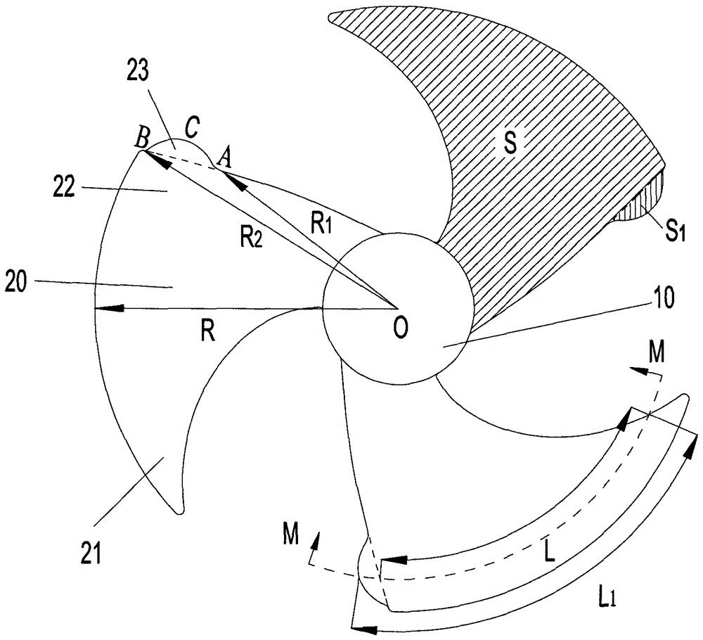
[0043] Such as Figure 5 As shown, the distance R from the starting point A of the empennage 23 to the hub axis O 1 Equal to 0.77R, the distance R from the end point B of the empennage 23 to the hub axis O 2 Equal to R, the distance R between the end C of the empennage 23 and the hub axis O 3 Equal to 0.98R, the length of the chord line from the leading edge 21 to the end C of the empennage 23 is L C Equal to 1.12L, the surface area of ​​empennage 23 is S 1Equal to 0.04S, the angle α between the centerline of the empennage 23 in the thickness direction and the normal line of the tailing edge 22 ranges from 88° to 92°, the thickness of the empennage 23 is equal to the thickness of the tailing edge 22, and the outer edge contour of the empennage 23 Consists of multiple smooth transition arcs.

Embodiment 2

[0045] Such as Figure 6 As shown, the distance R from the starting point A of the empennage 23 to the hub axis O 1 Equal to 0.8R, the distance R from the end point B of the empennage 23 to the hub axis O 2 Equal to R, the distance R between the end C of the empennage 23 and the hub axis O 3 Equal to 0.88R, the length of the chord line from the leading edge 21 to the end C of the empennage 23 is L C Equal to 1.15L, the surface area of ​​empennage 23 is S 1 Equal to 0.06S, the angle α between the centerline of the empennage 23 in the thickness direction and the normal line of the trailing edge 22 ranges from 90° to 94°, the thickness of the empennage 23 is slightly greater than the thickness of the tailing edge 22, and the outer edge profile It is in the form of a spline curve, that is, given multiple fixed points, two adjacent fixed points are connected by a curve.

[0046] According to the above parameters, use the same material and process to manufacture the axial flow f...


PUM


Abstract

The invention discloses an axial flow fan blade and an air conditioner provided with the same. The axial flow fan blade comprises a hub and multiple blade bodies arranged in the axial direction of the hub. Each blade body comprises a front edge and a tail edge, a tail wing is additionally arranged on the outer side of each tail edge, the edge of the outer side of each tail wing protrudes backward relative to the corresponding tail edge, the outline of the edge of the outer side of each tail wing is in a smooth curve shape, the radius of each blade body is defined to be R, the distance from the starting point A of each tail wing to the axial center O of the hub is R1, the distance between the finishing point B of each tail wing to the axial center O of the hub is R2, the ratio of R1 to R ranges from 0.70 to 0.88, and the ratio of R2 to R ranges from 0.96 to 1.00. By means of the axial flow fan blade, the tail wings are additionally arranged on the tail edges, so that the area of the fan blade is increased. Through design of the shapes and the positions of the tail wings, performance and efficiency of the fan blade are improved, and meanwhile noise of the fan blade is lowered.

Description

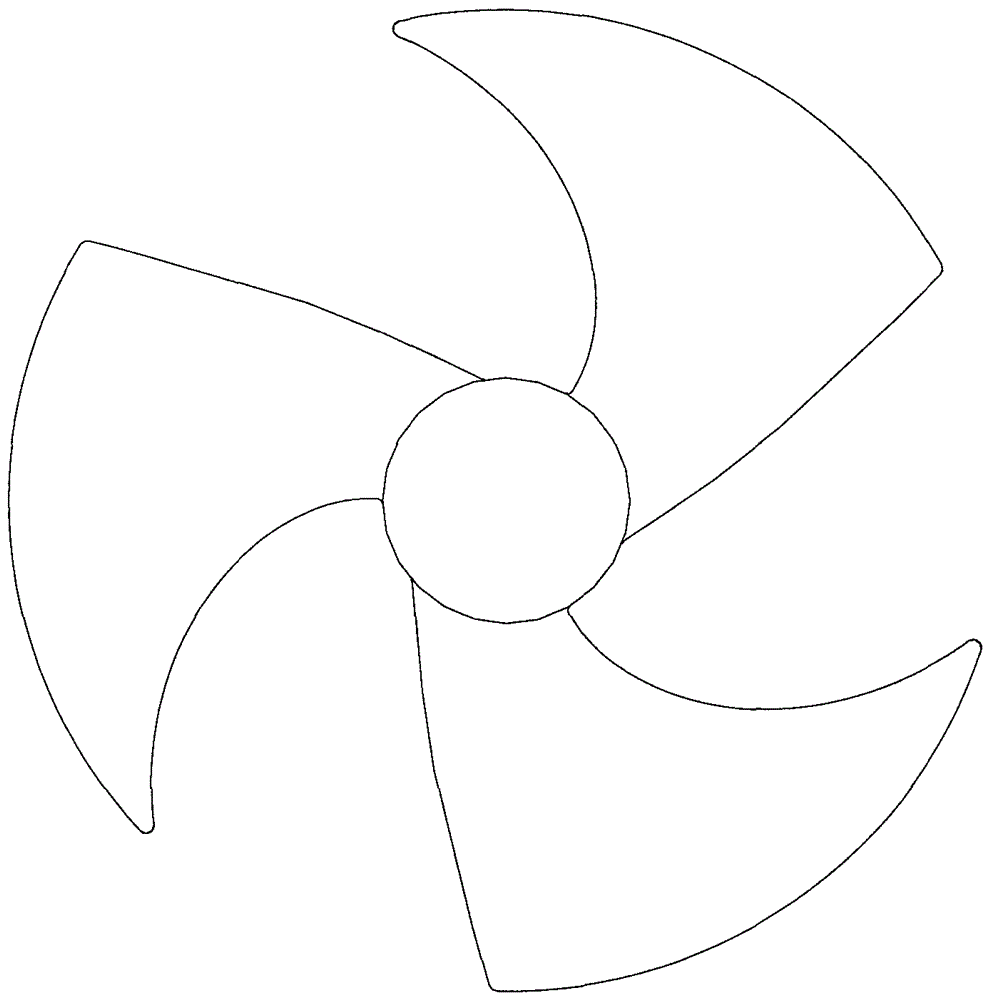
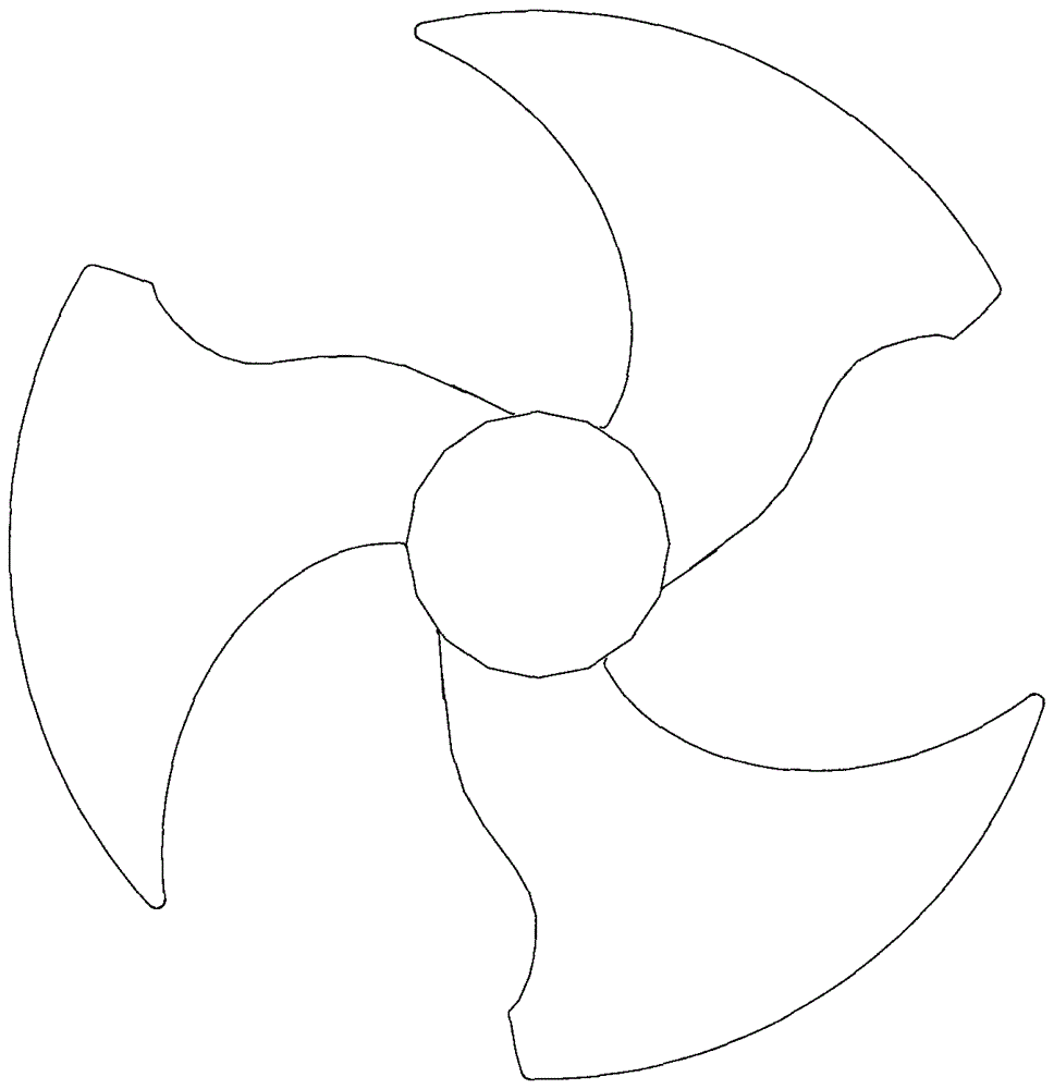
technical field [0001] The invention relates to a fan blade, in particular to an axial flow fan blade and an air conditioner having the same. Background technique [0002] With the continuous development of the air-conditioning industry and people's higher and higher energy efficiency requirements for air-conditioning, each component system of the air-conditioning requires lower power consumption and better performance. As the axial flow fan blades used for heat dissipation of the outdoor unit of the air conditioner, its performance and efficiency also need to be improved. How to effectively improve its air volume performance under the premise of power consumption and power consumption is a problem that plagues designers. [0003] Such as figure 1 and 2 As shown, the two most common axial-flow blades in the prior art are respectively axial-flow blade 1 and axial-flow blade 2, wherein axial-flow blade 2 is made on the basis of axial-flow blade 1 According to the modificat...

Claims


Application Information

Patent Timeline
Patent Type & Authority Patents(China)
IPC IPC(8): F04D29/38
Inventor 龙斌华刘中杰梁剑涛曹锋
Owner GREE ELECTRIC APPLIANCES INC
Learn More