Automobile fuel pump with improved NVH performance

A fuel pump and automobile technology, which is applied to liquid fuel feeders, charging systems, machines/engines, etc., can solve problems such as adverse effects on interior noise quality, turbulence, and fuel pump vibration, and improve interior noise. Experience the effect of comfort, simple structure design, and improved noise quality

Inactive Publication Date: 2021-10-26
FAW CAR CO LTD
View PDF8 Cites 0 Cited by
  • Summary
  • Abstract
  • Description
  • Claims
  • Application Information

AI Technical Summary

Problems solved by technology

Due to the high speed of the fuel pump motor, the pumped fuel flow is relatively large, and turbulent flow is prone to occur when passing through the pressure regulating valve and the subsequent fuel flow channel, resulting in eddy current disturbance
As a result, the vibration of the fuel pump will be intensified, resulting in "humming" vibration noise, and "squeaking" fluid disturbance noise
[0003] The above-mentioned NVH noise and abnormal noise problems of the fuel pump will have a negative impact on the noise quality inside the car, and will easily cause complaints from the drivers and passengers in the car

Method used


Image

  • Automobile fuel pump with improved NVH performance
  • Automobile fuel pump with improved NVH performance
  • Automobile fuel pump with improved NVH performance

Examples


Embodiment 1

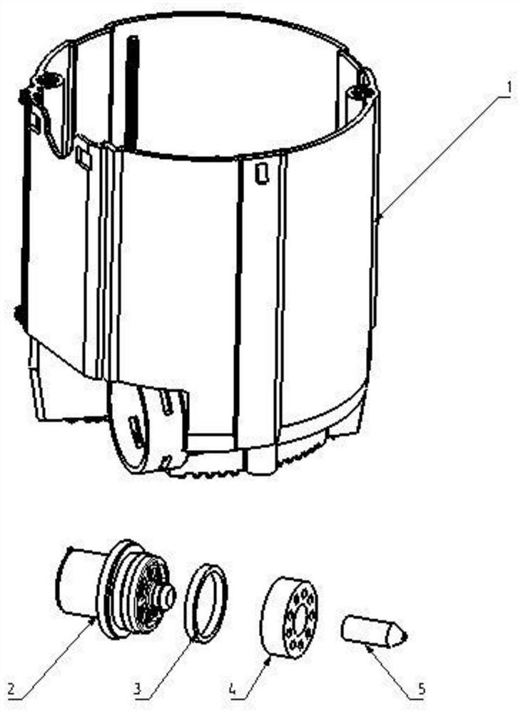
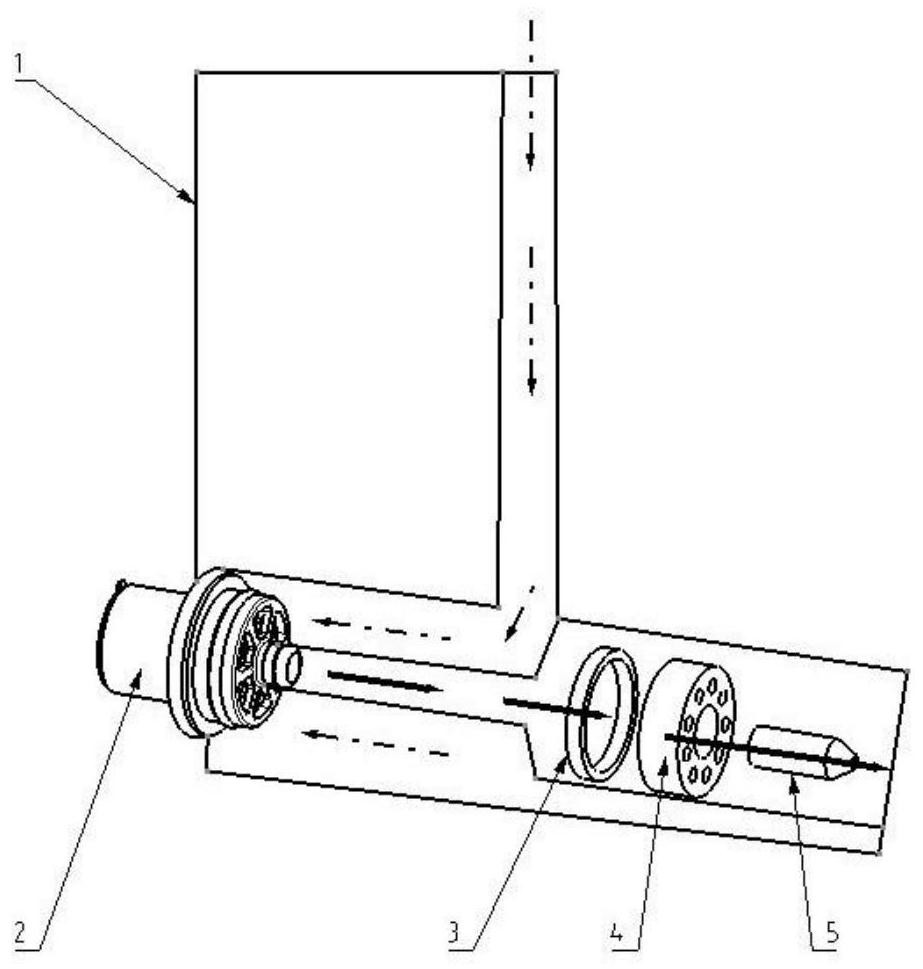
[0042] Such as figure 1 As shown, the block 3 and the damper 4 are placed in front of the inlet of the pressure regulating valve 2. If the layout space is limited, the block 3 may not be added. The fuel pumped by the fuel pump motor passes through the oil return channel of the oil storage tank 1, First, rectify through the damper 4, then enter the interior of the pressure regulating valve 2 from the inlet, then flow out from the outlet of the pressure regulating valve 2, and finally flow into the interior of the oil storage barrel 1 through the ejector pump 5.

Embodiment 2

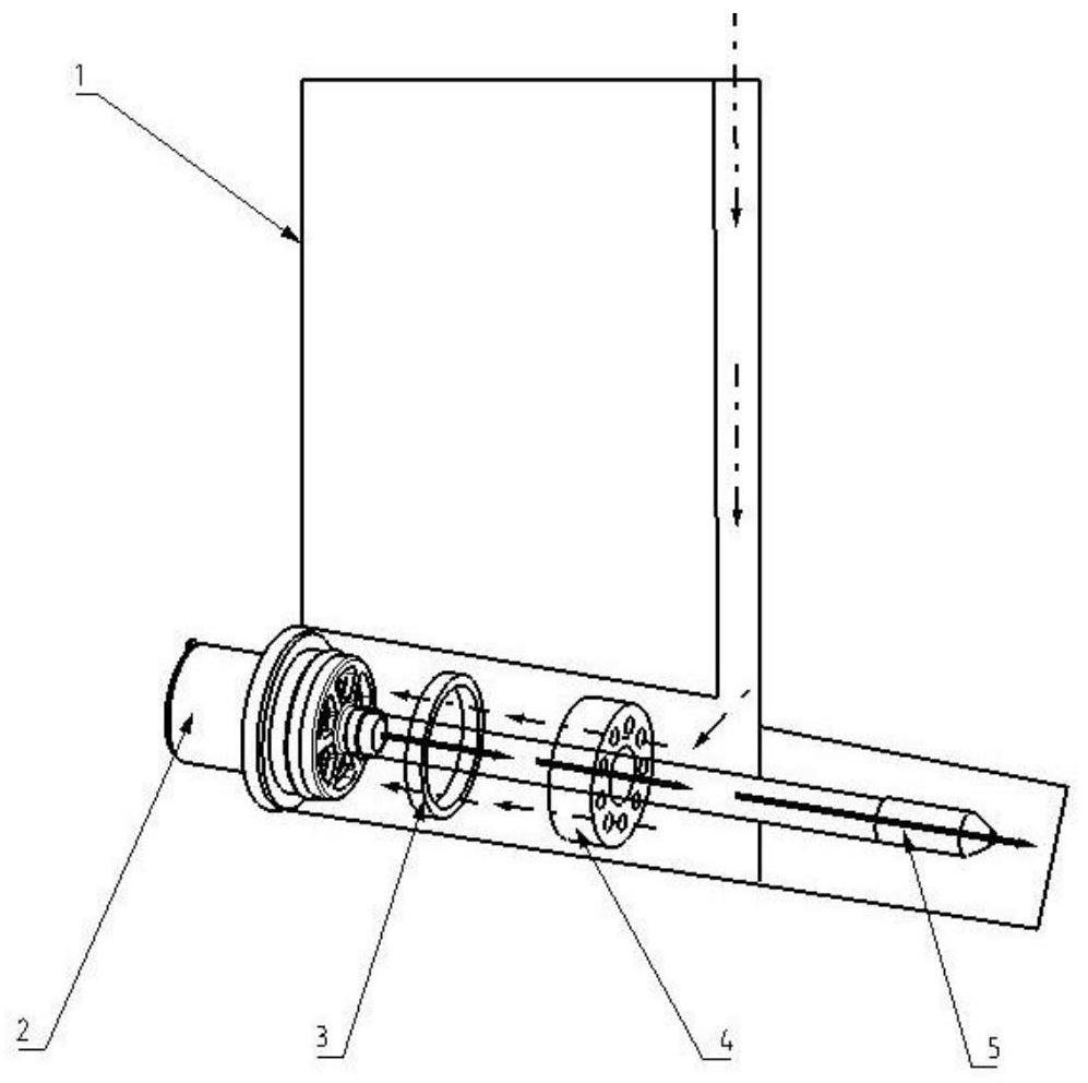
[0044] As shown in Figure 2, the stopper 3 and the damper 4 are placed behind the outlet of the pressure regulating valve 2. If the layout space is limited, the stopper 3 may not be added. The oil flow channel first enters the interior of the pressure regulating valve 2, then flows out from the outlet of the pressure regulating valve 2, then enters the ejector pump 5 through the damper 4, and finally flows into the oil storage barrel 1. Both of the above two methods make the turbulent flow state of the return oil rectified and improved after flowing through the damper 4, which optimizes the fuel pump vibration and fluid disturbance state to a large extent, and the NVH performance of the fuel pump is significantly improved. Reduce the noise of the fuel pump in the field, improve the noise quality of the fuel pump in the car, and improve the noise experience comfort of the driver and passengers in the car.


PUM


Abstract

The invention discloses an automobile fuel pump with improved NVH performance. The automobile fuel pump comprises an oil storage barrel, a pressure regulating valve, a damper and a jet pump, a fuel oil runner is arranged in the oil storage barrel, and a pressure regulating valve mounting hole is formed in the bottom of the fuel oil runner; the pressure regulating valve is connected to the pressure regulating valve mounting hole of the oil storage barrel in a pressed mode and is in interference fit with the pressure regulating valve mounting hole; the damper is on the pressure regulating valve in a pressed mode and is in interference fit with the pressure regulating valve; and the jet pump is connected in a center hole of the damper in a pressed mode and is in interference fit with the center hole. Return oil of the oil storage barrel enters an inlet of the pressure regulating valve through the fuel oil runner, and the pressure regulating valve is used for providing and maintaining oil supply pressure and achieving oil return through an inner valve body of the pressure regulating valve; through holes are formed in the damper in the fuel oil flowing direction, the fuel oil flowing hindering and rectifying effects are achieved, and fuel return disturbance is improved; and the return oil generates negative pressure after passing through the jet pump, and fuel oil outside the oil storage barrel is sucked into the oil storage barrel.

Description

technical field [0001] The invention relates to automobile fuel pump components, in particular to an automobile fuel pump structure for improving NVH performance. Background technique [0002] At present, from the perspective of structural integration and cost optimization, the design of automotive fuel pumps basically adopts the form of no oil return, that is, the fuel pumped by the fuel pump motor is self-returned through the pressure regulating valve inside the fuel pump. As the power performance of the engine continues to improve, the maximum fuel consumption of the engine will continue to increase, and the demand for the fuel supply of the fuel pump in the fuel tank will also continue to increase. When the vehicle is idling, due to the low engine speed and small throttle opening, the fuel supply of the fuel pump required by the engine is relatively small, and the inside of the fuel pump is almost in a state of full oil return, that is, the fuel pump motor pumps out Alm...

Claims


Application Information

Patent Timeline
Patent Type & Authority Applications(China)
IPC IPC(8): F02M37/00F02M37/08
CPCF02M37/0041F02M37/0052F02M37/0076F02M37/08
Inventor 李菁雨黄贵龙金永镇王岩涛张亚松赵昆
Owner FAW CAR CO LTD
Why Eureka
Try Eureka