
Combustion chamber for a turbomachine including improved air inlets

a combustion chamber and turbomachine technology, which is applied in the direction of machines/engines, efficient propulsion technologies, lighting and heating apparatus, etc., can solve the problems of uniform fuel concentration in the primary zone of the combustion chamber, insufficient temperature profile of the combustion gases being expelled from the combustion chamber,

Active Publication Date: 2012-06-07
SN DETUDE & DE CONSTR DE MOTEURS DAVIATION S N E C M A
View PDF16 Cites 6 Cited by
  • Summary
  • Abstract
  • Description
  • Claims
  • Application Information

AI Technical Summary

Benefits of technology

[0012]One aim of the invention is notably to provide a simple, economic and efficient solution to these problems.

Problems solved by technology

And in combustion chambers of known types, the air-fuel blend generally remains in the primary zone for a time which is not long enough to allow complete combustion.
In addition, the temperature profile of the combustion gases being expelled from these combustion chambers is not sufficiently uniform to allow optimum operation of the turbines associated with these combustion chambers.
This results notably from the non-uniformity of the fuel concentration in the primary zone of these chambers.

Method used


Image

  • Combustion chamber for a turbomachine including improved air inlets
  • Combustion chamber for a turbomachine including improved air inlets
  • Combustion chamber for a turbomachine including improved air inlets

Examples


Embodiment Construction

[0012]One aim of the invention is notably to provide a simple, economic and efficient solution to these problems.

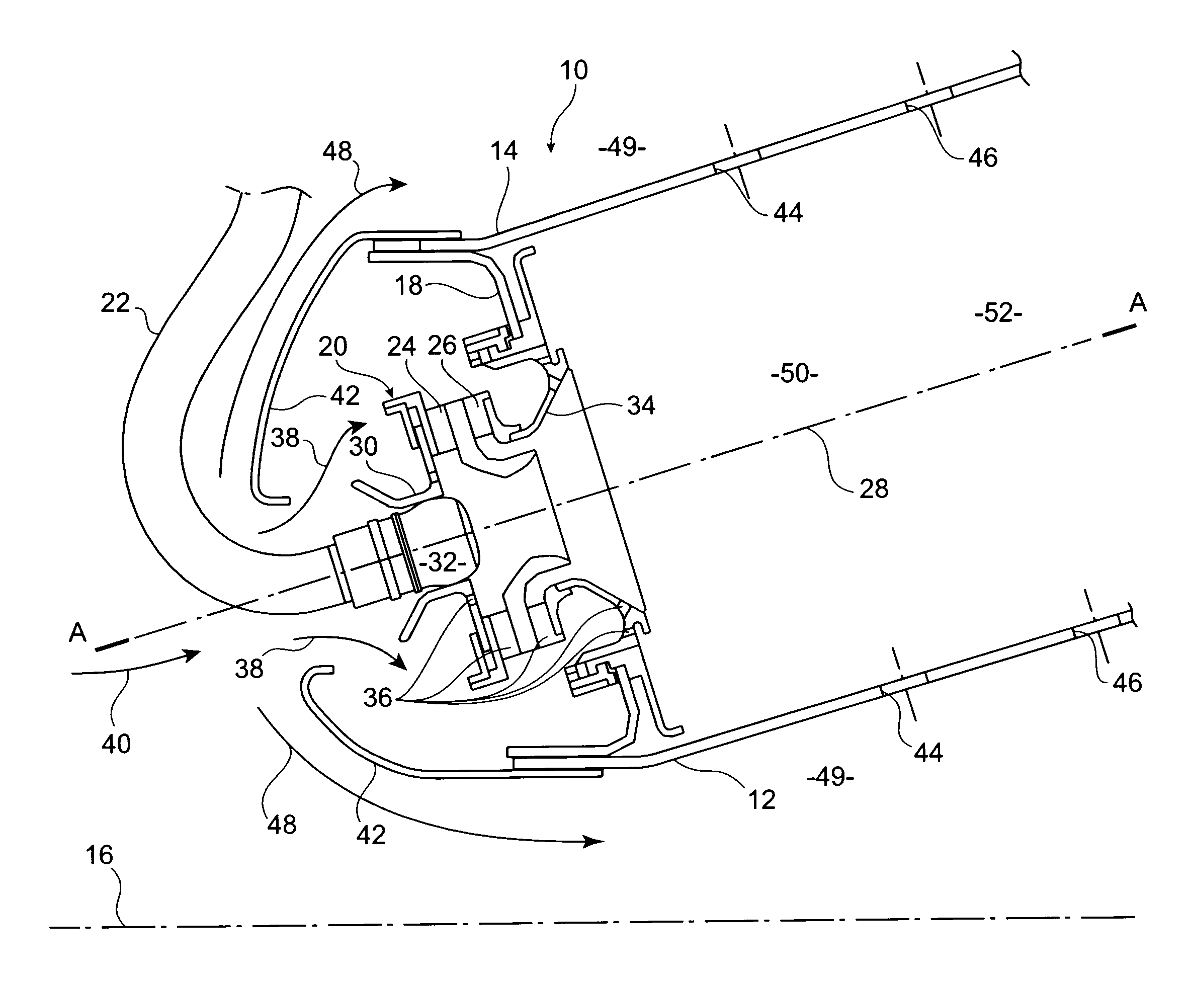
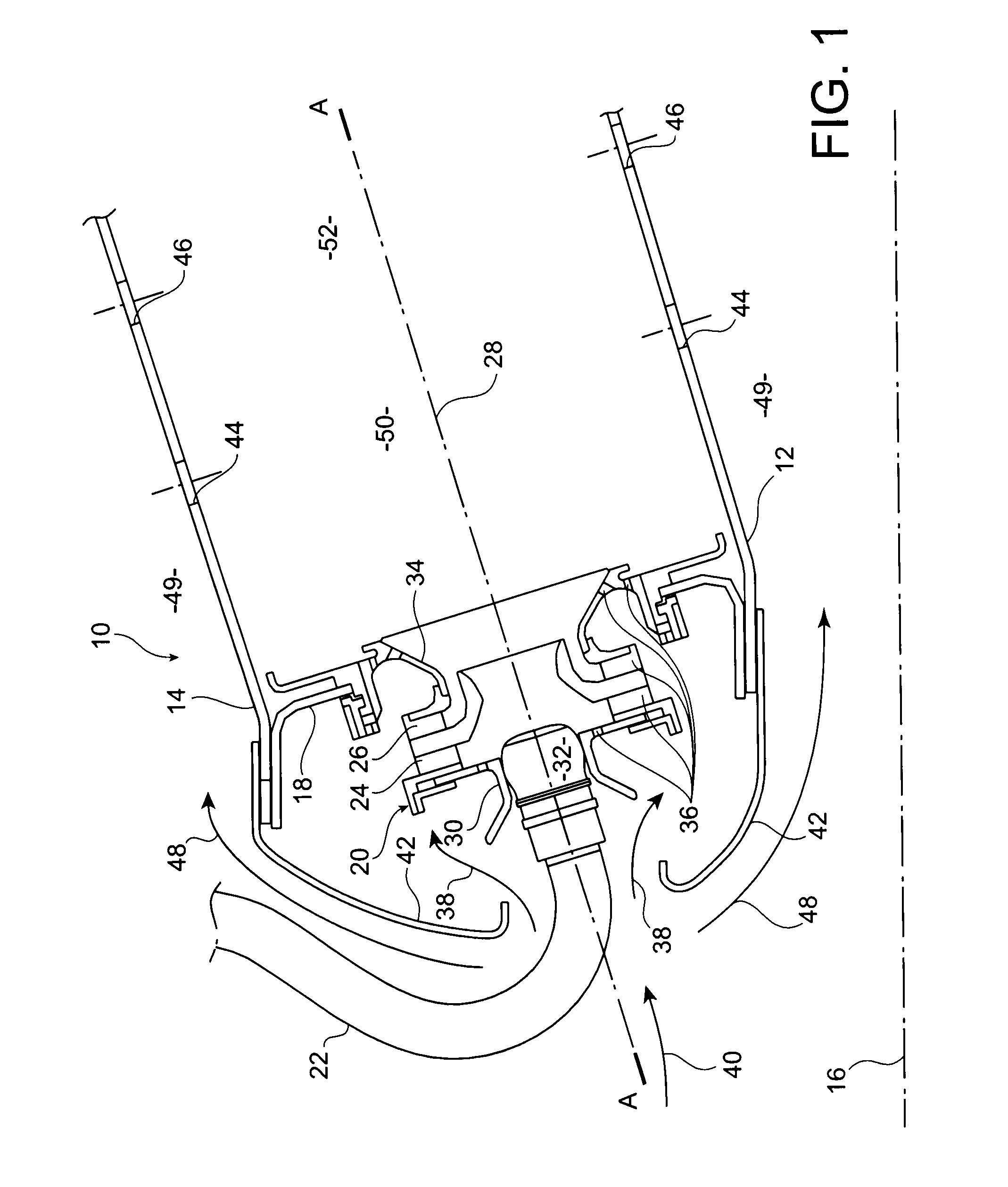
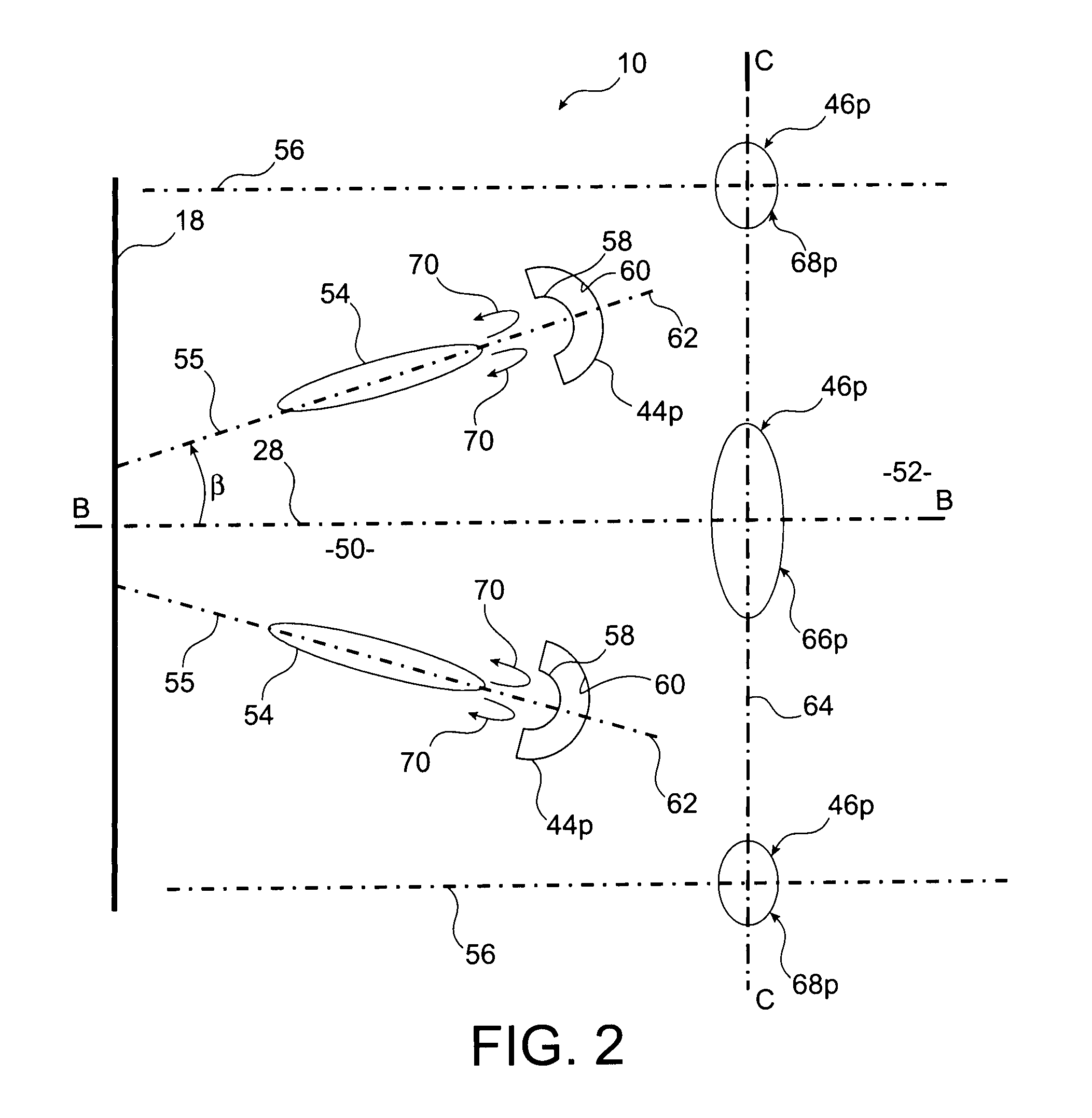
[0013]To this end it proposes a combustion chamber for a turbomachine, including an annular end wall fitted with injection systems regularly distributed around a longitudinal axis of the combustion chamber, each of which has a central fuel emission axis, where the combustion chamber also includes two coaxial annular walls, which are respectively internal and external, connected to one another by the end wall, and including multiple air inlets formed on at least one of these annular walls and opening radially towards the outside relative to the axis of the combustion chamber. According to the invention, the multiple air inlets include inlets of a first type shaped such that the orthogonal projection of each of these inlets in a corresponding projection plane, which passes through the central axis of the injection system closest to the inlet, and which is perpendicular to a...


PUM


Abstract

A combustion chamber for a turbomachine, including two coaxial walls including air inlets, each of which is configured such that its orthogonal projection, in a plane passing through the axis of the injection system closest to the inlet and perpendicular to an axial plane passing through this axis and through the axis of the combustion chamber, has an upstream edge of convex shape when seen from downstream.

Description

TECHNICAL FIELD[0001]The present invention relates to the field of turbomachines, such as aircraft turbomachines, and concerns more specifically annular combustion chambers of turbomachines.STATE OF THE PRIOR ART[0002]Turbomachines include at least one turbine positioned at the outlet of a combustion chamber to extract energy from a primary flow of gases injected by this combustion chamber, and to drive a compressor positioned upstream of the combustion chamber, and supplying this chamber with pressurised air.[0003]Combustion chambers of turbomachines typically include two coaxial annular walls, which are respectively radially internal and radially external, which extend from upstream to downstream, in the direction of flow of the primary gas flow in the turbomachine, around the axis of the combustion chamber, and which are connected to one another at their upstream end by an annular end wall at the back of the chamber which extends roughly radially around the abovementioned axis. T...

Claims


Application Information

Patent Timeline
Patent Type & Authority Applications(United States)
IPC IPC(8): F23R3/42
CPCF23R3/06Y02T50/675F23R3/50Y02T50/60
Inventor SANDELIS, DENIS JEAN MAURICE
Owner SN DETUDE & DE CONSTR DE MOTEURS DAVIATION S N E C M A
Learn More