Radio antenna

a radio antenna and reflector technology, applied in the direction of antennas, antenna details, wind-induced force reduction, etc., can solve the problems of increased manufacturing precision, insufficient reflectivity properties of perforated reflectors of the type described above, and insufficient acoustic stress resistance of antennae obtained in this manner, so as to achieve maximum contact area

Inactive Publication Date: 2014-10-28
ASTRIUM SAS
View PDF9 Cites 0 Cited by
  • Summary
  • Abstract
  • Description
  • Claims
  • Application Information

AI Technical Summary

Benefits of technology

[0015]One aim of the invention is notably to provide a simple, economic and efficient solution to these problems, allowing the abovementioned disadvantages to be avoided.
[0016]Its goal is notably a radio antenna for space satellite, capable of operating at the frequencies of the Ka band, and satisfying the requirements imposed on this type of antenna, notably in respect of the sensitivity of the antenna to the vibratory stresses caused by the launchers, the precision of manufacture of the profile of the antenna's reflector and the stability of this profile over time and, generally, the antenna's thermomechanical properties in orbit.
[0017]The invention proposes to this end a radio antenna, particularly for a spacecraft, including a reflector and means of support of this reflector, where the reflector includes a front skin able to reflect radio waves, and a rigid rear structure supported by the means of support, where the reflector includes a layer of elastic material which is interposed between the front skin and the rigid rear structure, and which is able to dampen the vibrations of the front skin.

Problems solved by technology

However, the reflectivity properties of the perforated reflectors of the type described above are not satisfactory at frequencies of approximately between 20 GHz and 40 GHz (Ka band).
Solutions have been proposed, which consist, using an antenna of the type described above, in reducing the dimensions of the perforations of the active skin, or even in replacing the perforated active skin by an unperforated skin, but the antennae obtained in this manner have proved to be too sensitive to acoustic stresses.
Moreover, at these higher frequencies, the tolerances relative to the profiles of the reflectors are stricter, leading to more severe requirements in terms of manufacturing precision, and of stability over time of the reflectors, typically of the order of 30 μm RMS, which should be compared with 150 μm RMS in the case of satellites operating at the lower frequencies of the Ku band.
And the sandwich structures of the type described above, which include skins formed from a single sheet of composite material, do not easily allow the criteria inherent to operation in the Ka band to be satisfied.

Method used


Image

  • Radio antenna
  • Radio antenna

Examples


Embodiment Construction

[0052]The invention will be better understood, and other details, advantages and characteristics of it will appear, on reading the following description given as a non-restrictive example, and with reference to the appended illustrations, in which:

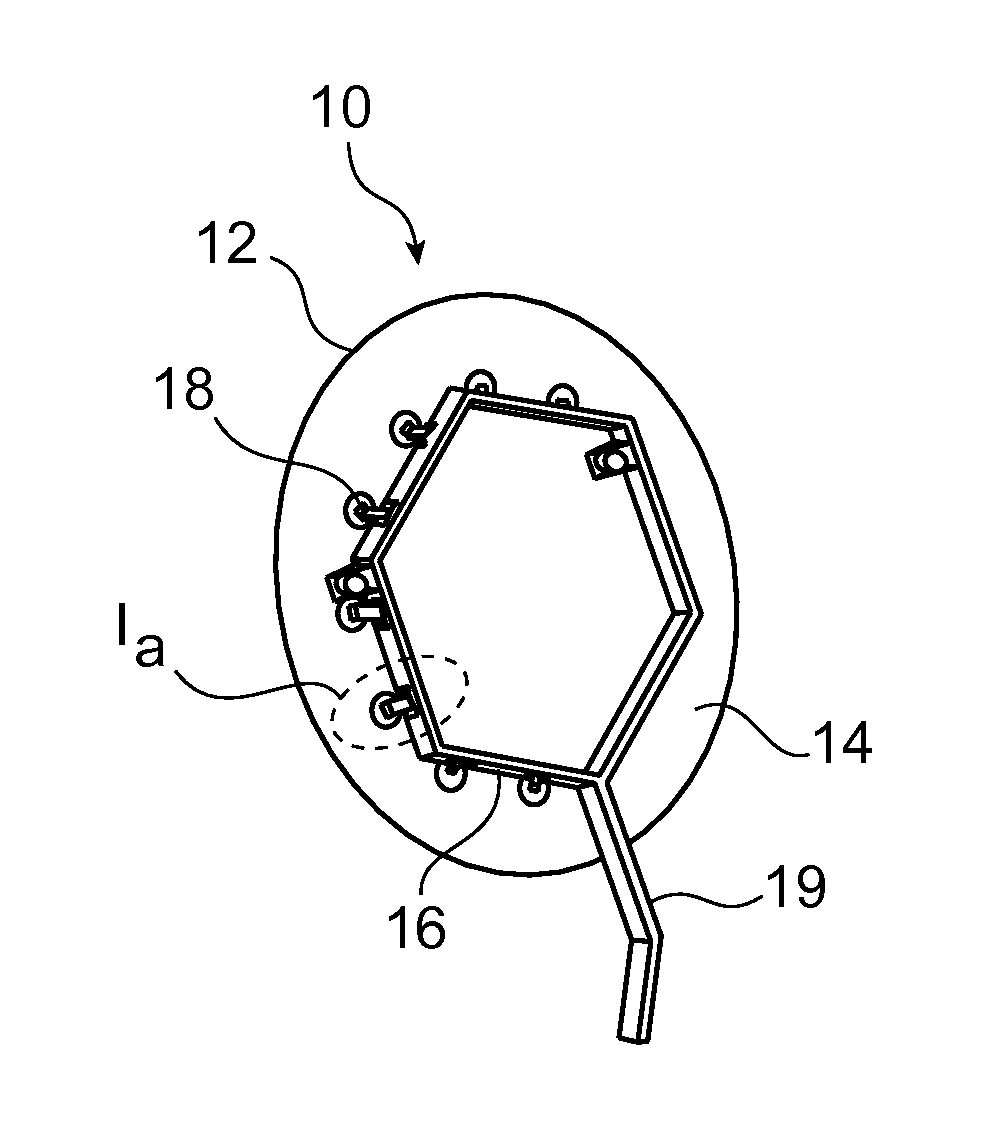
[0053]FIG. 1, which has already been described, is a schematic perspective view of a radio antenna of a known type;

[0054]FIG. 1a, which has already been described, is a larger-scale view of detail 1a of FIG. 1;

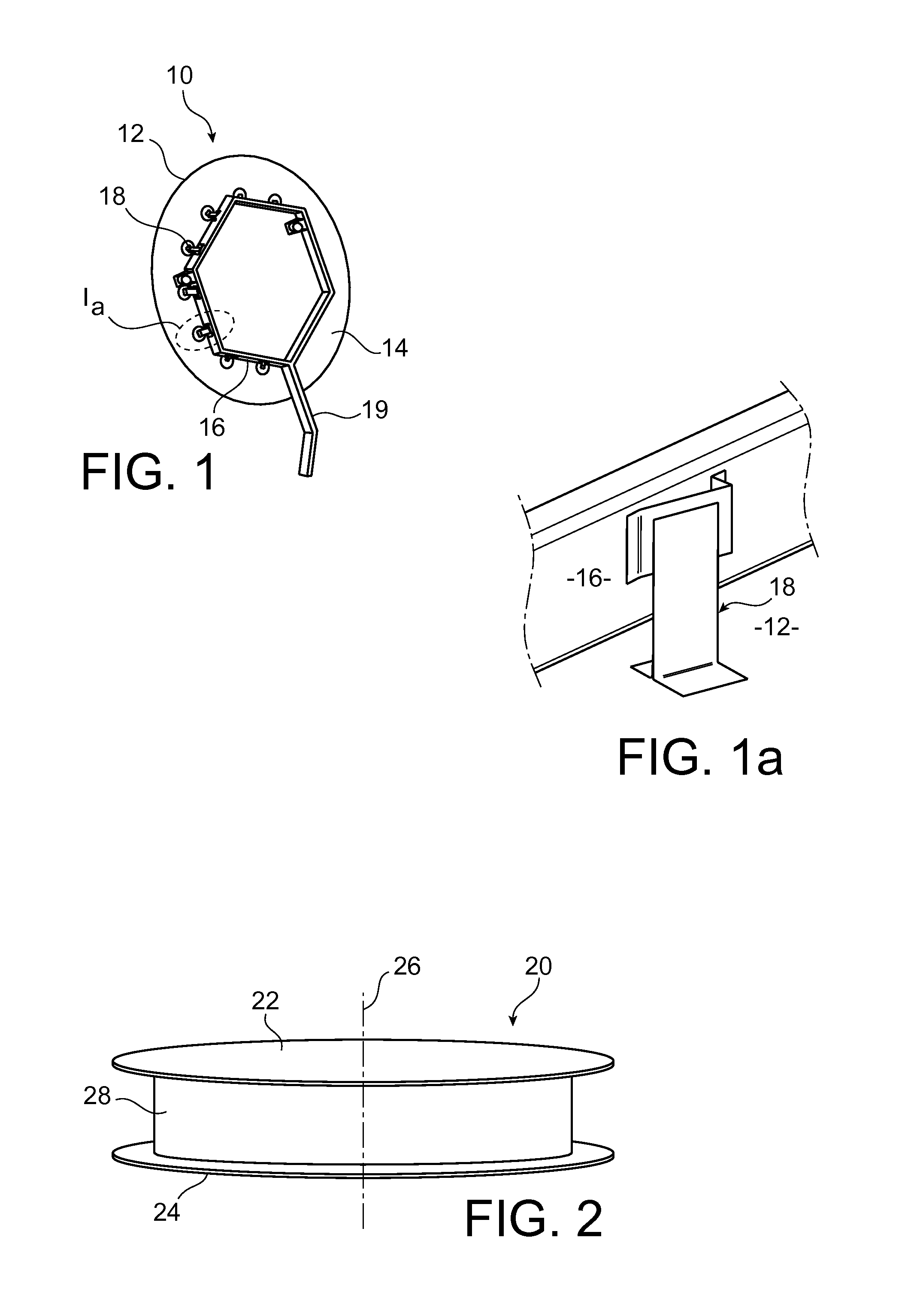
[0055]FIG. 2 is a schematic perspective view of the reflector of a radio antenna according to the invention.

DETAILED DESCRIPTION OF A PREFERRED EMBODIMENT

[0056]FIG. 2 represents a reflector 20 of a radio antenna for a spacecraft according to a preferred embodiment of the invention.

[0057]Reflector 20 includes a front skin 22, sometimes also called the active skin, and a rear structural skin 24 supported by a support arm (not represented in FIG. 2), intended to provide the connection between the antenna and a spacecraft.

[0058]In the re...


PUM


Abstract

The invention concerns a radio antenna for a space satellite, including a reflector and means of support of this reflector. The reflector includes a front skin able to reflect radio waves, a rigid rear structure supported by the means of support, and a layer of elastic material interposed between said front skin and said rigid rear structure, able to dampen the vibrations of the front skin.

Description

TECHNICAL FIELD[0001]The present invention relates to the field of reflector radio antennae, and concerns in particular an antenna for a spacecraft, such as a telecommunications satellite.STATE OF THE PRIOR ART[0002]The antennae of spacecrafts must satisfy specifications notably concerning the reflectivity of their reflectors, but also the mechanical properties of the fastenings of the reflectors to the spacecrafts, which are subject to the vibratory, acoustic and dynamic stresses caused by space launchers. These antennae must also satisfy specifications concerning their thermoelastic properties in orbit.[0003]Since the level of acoustic stresses caused by the launchers is very difficult to predict, it is preferable that these antennae should be almost insensitive to acoustic efforts, in order to limit the risks of under-dimensioning or over-dimensioning of the reflectors' fastenings to the spacecrafts.[0004]FIGS. 1 and 1a represent an example of a radio antenna 10 (FIG. 1) for a te...

Claims


Application Information

Patent Timeline
Patent Type & Authority Patents(United States)
IPC IPC(8): H01Q19/10H01Q15/16H01Q1/00
CPCH01Q15/16H01Q1/005
Inventor DESAGULIER, CHRISTIAN
Owner ASTRIUM SAS
Why Eureka
Try Eureka