Ignition device and method for a turbomachine combustion chamber

a technology of ignition device and combustion chamber, which is applied in the direction of machines/engines, mechanical equipment, lighting and heating apparatus, etc., can solve the problems of electric power modules contributing to the failure risk of ignition plugs, and achieve the effect of simple, economic and efficien

Active Publication Date: 2016-10-11
SN DETUDE & DE CONSTR DE MOTEURS DAVIATION S N E C M A
View PDF8 Cites 1 Cited by
  • Summary
  • Abstract
  • Description
  • Claims
  • Application Information

AI Technical Summary

Benefits of technology

[0012]One object of the invention is in particular to provide a simple, economic and efficient solution to these problems.

Problems solved by technology

Furthermore, the electric power modules contribute to the failure risk of ignition plugs.

Method used


Image

  • Ignition device and method for a turbomachine combustion chamber
  • Ignition device and method for a turbomachine combustion chamber
  • Ignition device and method for a turbomachine combustion chamber

Examples


first embodiment

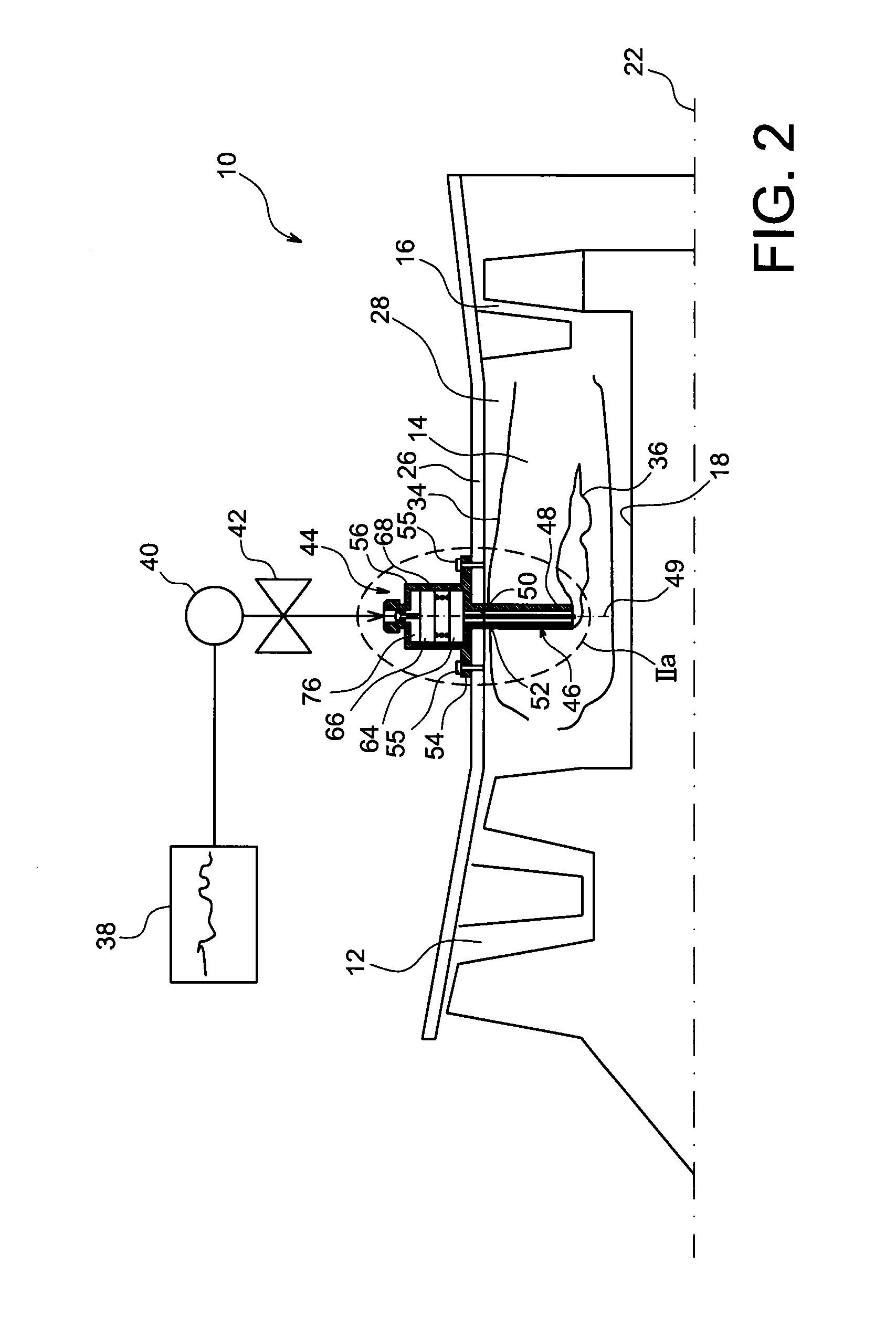
[0088]FIGS. 2 and 2a illustrate a turbomachine, for example an airplane turbojet engine, comprising an ignition device 44 of its annular combustion chamber 14 according to the invention.

[0089]In the following, the axial and radial directions are defined with respect to the longitudinal axis 22 of the turbomachine.

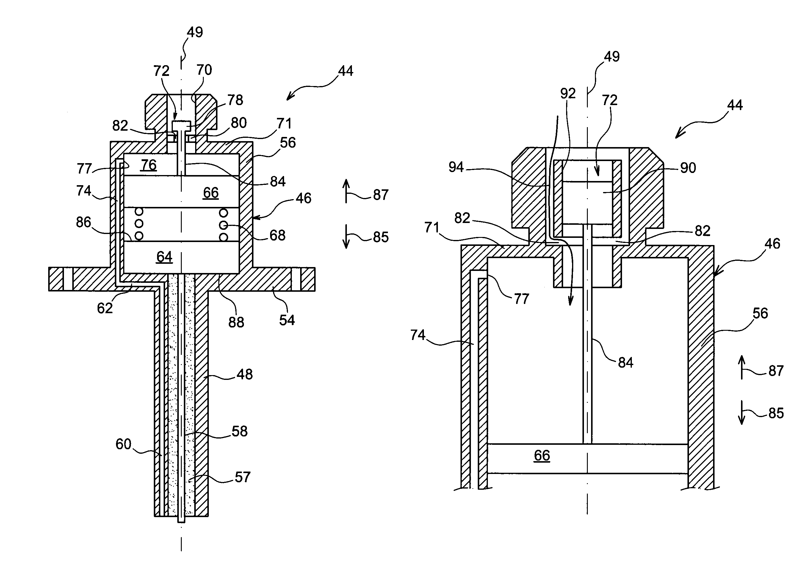
[0090]The ignition device 44 includes a body 46 integrating an ignition plug, a module for electrically powering this plug, as well as a starting injector, as will be more clearly apparent in the following.

[0091]The body 46 comprises a cylinder shaped elongated first part 48, having for example a revolution symmetry about an axis 49, and which extends through a port 50 of the outer case 26 of the combustion chamber and a port 52 of the outer wall 34 of this combustion chamber.

[0092]The body 46 further comprises a plate 54 connected to a radially outer end of the aforesaid first part 48 and enabling this body 46 to be attached to an external surface of the outer case 26 of t...

second embodiment

[0127]In this second embodiment of the invention, the piston 66 of the device 44 can continue its displacement in the direction of increase in the volume of the fluid flow chamber 76 even when the valve 72 is closed, without this piston 66 being retained by the sealing element 90 of the valve 72.

[0128]Because of the absence of a stop forming element against the movable assembly comprising the piston 66, the oscillations of this piston 66 can be highly even.

[0129]It should be noted that the movement of this movable assembly is then substantially determined by the stiffness of the elastic means 68, the mass of this movable assembly and the fluid pressure, as well as the frictions induced during the movement of this movable assembly.

[0130]Other configurations of the valve 72 are of course possible without departing from the scope of the present invention.

[0131]Generally, the ignition device 44 according to the invention has the advantage of not requiring external electric power as is t...


PUM


Abstract

A method and device for igniting a turbomachine combustion chamber including alternately: an intake phase of a fluid into a chamber through an intake port, during which a piston compresses an elastic mechanism under pressure of the fluid such that the elastic mechanism applies onto a piezoelectric element a force sufficient for the piezoelectric element to induce between the electrodes an electric voltage enabling an electric arc to be generated, until the piston reaches a predetermined position for closing a valve for sealing the intake port; and an exhaust phase of the fluid, during which the elastic mechanism pushes back the piston to induce a fluid ejection out of the chamber through an exhaust port, and the valve is open.

Description

TECHNICAL FIELD[0001]The present invention relates to the ignition of combustion chambers in turbomachines, in particular aircraft turbomachines such as turbojet engines and turboprop engines of airplanes.[0002]The invention relates in particular to an ignition device for a turbomachine combustion chamber, comprising two electrodes forming an ignition plug, and a module for electrically powering these electrodes.[0003]It also relates to a combustion chamber equipped with such a device, a turbomachine comprising a combustion chamber of this type, as well as a method for igniting such a combustion chamber.STATE OF PRIOR ART[0004]FIG. 1 represents a simplified example of an aircraft turbomachine 10 of a known type, comprising, from upstream to downstream along the general gas flow direction, a compressor 12, a combustion chamber 14, and a turbine 16 designed to drive the compressor 12 through a common shaft 18 under the effect of the thrust of gases from the combustion chamber 14, in a...

Claims


Application Information

Patent Timeline
Patent Type & Authority Patents(United States)
IPC IPC(8): F02C7/264F23Q3/00F02C7/266
CPCF02C7/264F02C7/266F23Q3/002F23Q3/008F23R2900/00
Inventor JUCHAULD, ETIENNEBADINIER, JEAN-PIERREROBERDEAU, JEAN PIERRESERRAU, MARC
Owner SN DETUDE & DE CONSTR DE MOTEURS DAVIATION S N E C M A
Why Eureka
Try Eureka