Cell balance device and battery system

a battery system and cell balance technology, applied in the direction of charging equalisation circuit, transportation and packaging, battery arrangement for several simultaneous batteries, etc., can solve the problems of increased cost, low balance speed, low etc., and achieve the effect of enhancing the cell balance performance of the battery system and reducing the cos

Active Publication Date: 2012-06-07
ABLIC INC
View PDF14 Cites 24 Cited by
  • Summary
  • Abstract
  • Description
  • Claims
  • Application Information

AI Technical Summary

Benefits of technology

[0010]The present invention has been devised in view of the above-mentioned problems, and provides a cell balance device capable of enhancing cell balance performance and requiring no high voltage process, and a battery system including the cell balance devices.
[0013]According to the present invention, the battery system having the following effects can be provided.
[0014]Cell balance performance of the battery system can be enhanced. Even if the number of secondary batteries varies, the battery system can be designed correspondingly with ease. The battery system requires no high voltage process and can therefore be reduced in cost.

Problems solved by technology

In the conventional technology, however, only one voltage hold device (capacitor) is provided for the number of cells to be balanced, thus causing a problem that the battery system has low balance performance (low balance speed).
In addition, when the number of secondary batteries to be connected to the cell balance device increases, a higher voltage is applied to the cell balance device, and the cell balance device therefore needs to be manufactured through high voltage process, thus causing another problem of increased cost.

Method used


Image

  • Cell balance device and battery system
  • Cell balance device and battery system
  • Cell balance device and battery system

Examples


first embodiment

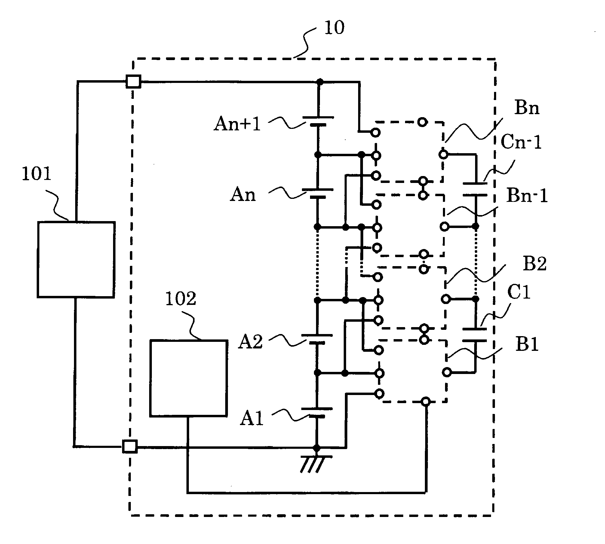
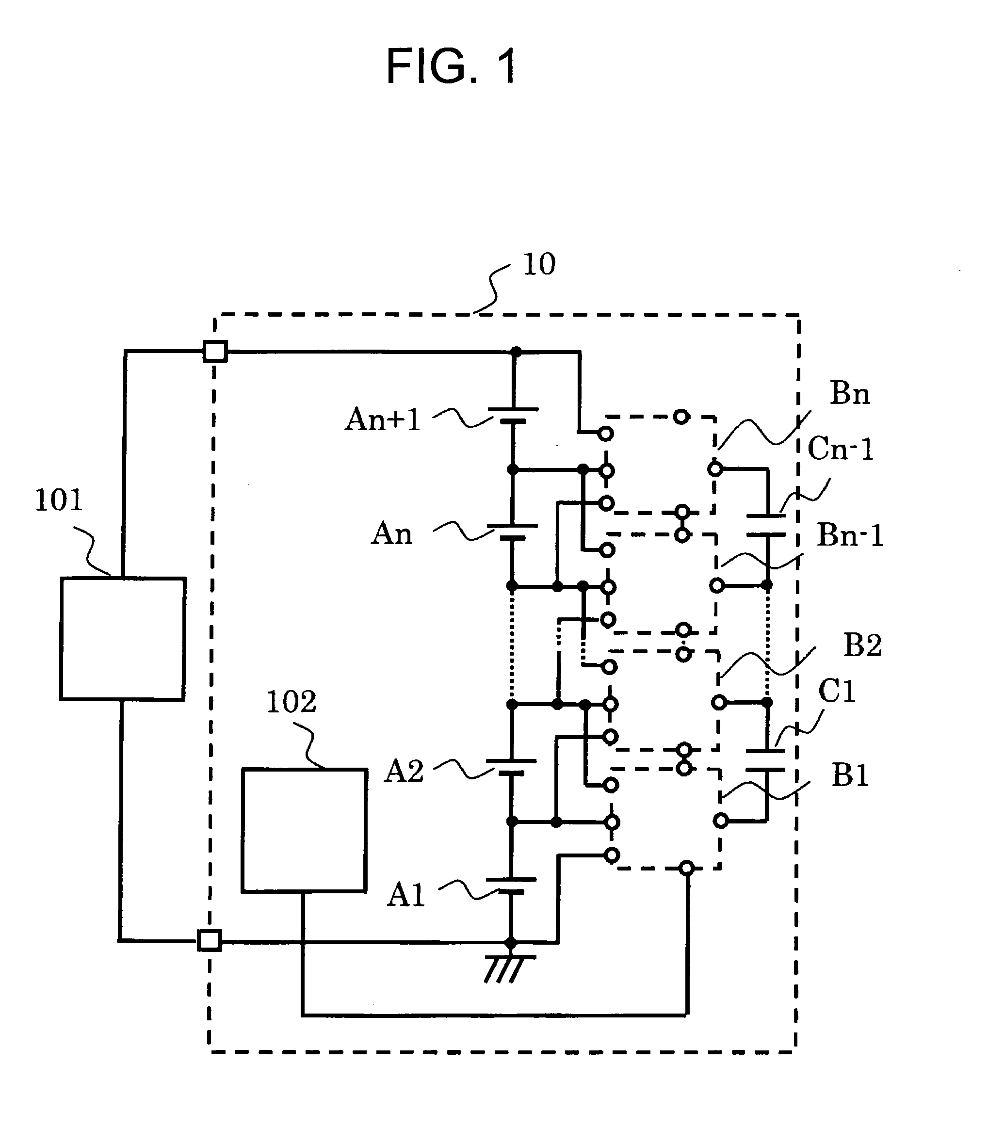
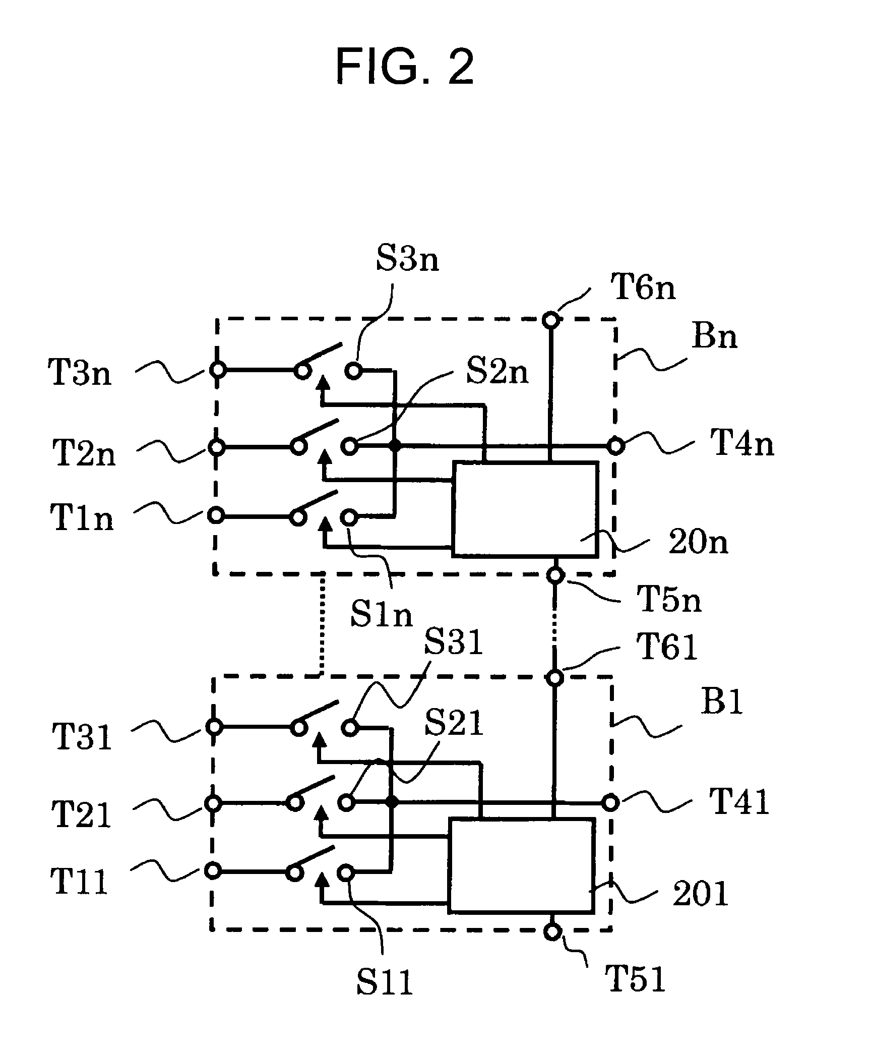
[0029]FIG. 1 is a circuit diagram of a battery system including cell balance devices according to a first embodiment of the present invention. FIG. 2 is a circuit diagram of the cell balance devices according to the first embodiment.

[0030]A battery system 10 of the first embodiment includes a clock generation circuit 102, n+1 secondary batteries A1 to An+1 connected in series, n cell balance devices B1 to Bn, n−1 voltage hold devices (capacitors) C1 to Cn−1, and external terminals to which a charger 101 or a load is to be connected (n is an integer of 2 or more).

[0031]The first cell balance device B1 includes switch circuits S11, S21, and S31, a control circuit 201, and terminals T11, T21, T31, T41, T51, and T61. The other cell balance devices B2 to Bn have the same configuration.

[0032]In the cell balance device B1, the terminal T11 is connected to a negative terminal of the secondary battery A1, the terminal T21 is connected to a positive terminal of the secondary battery A1 and a ...

second embodiment

[0047]FIG. 4 is a circuit diagram of a battery system including cell balance devices according to a second embodiment of the present invention. FIG. 5 is a circuit diagram of the cell balance devices according to the second embodiment. The second embodiment is different from the first embodiment in that a larger number of switch circuits are used in the cell balance device and the wiring of the battery system is changed correspondingly.

[0048]A battery system 11 of the second embodiment includes a clock generation circuit 102a, 2n+1 secondary batteries A1 to A2n+1 connected in series, n cell balance devices D1 to Dn, and 2n−1 voltage hold devices (capacitors) C1 to C2n−1 (n is an integer of 2 or more).

[0049]The first cell balance device D1 includes switch circuits S111, S121, S131, S141, S151, and S161, a control circuit 201, and terminals T111, T121, T131, T141, T151, T161, T171, and T181. The other cell balance devices D2 to Dn have the same configuration.

[0050]In the cell balance ...

third embodiment

[0066]FIG. 8 is a circuit diagram of a battery system including cell balance devices according to a third embodiment of the present invention. FIG. 9 is a circuit diagram of the cell balance devices according to the third embodiment.

[0067]A battery system 10 of the third embodiment includes a clock generation circuit 102, n+1 secondary batteries A1 to An+1 connected in series, n cell balance devices E1 to En, n−1 voltage hold devices (capacitors) C1 to Cn−1, and external terminals to which a charger 101 or a load is to be connected (n is an integer of 2 or more).

[0068]The first cell balance device E1 includes switch circuits S11, S21, and S31, a control circuit 201, and terminals T11, T21, T31, T41, T51, T61, T71, and T81. The terminal T71 is a reset signal receiving terminal and the terminal T81 is a reset signal transmitting terminal. The other cell balance devices E2 to En have the same configuration.

[0069]In the cell balance device E1, the terminal T11 and the terminal T71 are c...


PUM


Abstract

Provided are a cell balance device with high cell balance performance and high cell balance speed and requiring no high voltage process, and a battery system including the cell balance devices. The cell balance device includes: three terminals to be connected to secondary batteries; one terminal to be connected to a voltage hold device; three switches provided between the three terminals and the one terminal; and a receiving terminal and a transmitting terminal for a synchronization signal. Alternatively, the cell balance device includes: four terminals to be connected to secondary batteries; two terminals to be connected to a voltage hold device; six switches provided between the four terminals and the two terminals; and a receiving terminal and a transmitting terminal for a synchronization signal. The battery system includes: a plurality of secondary batteries; a plurality of voltage hold devices; a plurality of cell balance devices; and a clock generation circuit.

Description

RELATED APPLICATIONS[0001]This application claims priority under 35 U.S.C. §119 to Japanese Patent Application Nos. 2010-271808 filed on Dec. 6, 2010 and 2011-171316 filed on Aug. 4, 2011, the entire contents of which are hereby incorporated by reference.BACKGROUND OF THE INVENTION[0002]1. Field of the Invention[0003]The present invention relates to a cell balance device for achieving a cell balance of secondary batteries connected in series and a battery system including the cell balance devices, and more particularly, to a cell balance device capable of improving speed for achieving a cell balance with an inexpensive configuration and a battery system including the cell balance devices.[0004]2. Description of the Related Art[0005]FIG. 7 illustrates a circuit diagram of a conventional cell balance adjusting circuit. A cell balance device including the conventional cell balance adjusting circuit is provided with an assembled battery portion, in which a plurality of secondary battery...

Claims


Application Information

Patent Timeline
Patent Type & Authority Applications(United States)
IPC IPC(8): H02J7/00H02J7/02
CPCH02J7/0016H02J7/04
Inventor SAKURAI, ATSUSHISANO, KAZUAKISAITO, HIROSHI
Owner ABLIC INC
Why Eureka
Try Eureka