Supercharge Your Innovation With Domain-Expert AI Agents!

Lighting Apparatus

a technology of led string lamps and light fixtures, which is applied in the direction of lighting and heating apparatus, semiconductor devices for light sources, and support devices for lighting and heating. it can solve the problems of degrading the yield difficult to reduce the cost of led string lamps, and heavy led string lamps. achieve the effect of high manufacturing yield and efficiency

Inactive Publication Date: 2012-06-07
EVERLIGHT ELECTRONICS
View PDF7 Cites 0 Cited by
  • Summary
  • Abstract
  • Description
  • Claims
  • Application Information

AI Technical Summary

Benefits of technology

The solution enables a cost-effective, lightweight LED string lamp with improved weatherability and waterproofness, maintaining operational integrity under external forces and enhancing manufacturing yield and efficiency by securing the circuit board and conducting wires.

Problems solved by technology

However, in order to fill the internal space of the whole housing, a lot of encapsulant will be consumed, so it is difficult to reduce the cost of the LED string lamp, and the LED string lamp becomes heavier.
Furthermore, many air bubbles will appear when the internal surface of the housing is filled by a lot of encapsulant, thereby degrading the yield of the LED string lamp.
Furthermore, due to high consumption of the encapsulant, a long time period is needed before the curing of the encapsulant, resulting in difficulty in improving the production efficiency.
In addition, since the LEDs in the lighting apparatus and an external power are connected by a conducting wire, which is connected to the LEDs merely through solder joints by means of soldering, under the pulling force from the outside, the conducting wire will easily drop off from the solder joints due to the insufficient joint force, with the result that the LED string lamp cannot operate normally.
In another aspect, during a manufacturing process of the conventional LED string lamp, when the encapsulant is filled into the internal space of the housing, a circuit board carrying the LEDs may float on the encapsulant, and then the LEDs cannot be completely encapsulated by the encapsulant, which degrades the yield of the LED string lamp.

Method used


Image

  • Lighting Apparatus
  • Lighting Apparatus
  • Lighting Apparatus

Examples


Embodiment Construction

[0035]Reference will now be made in detail to the present preferred embodiments of the invention, examples of which are illustrated in the accompanying drawings. Wherever possible, the same reference numbers are used in the drawings and the description to refer to the same or like parts.

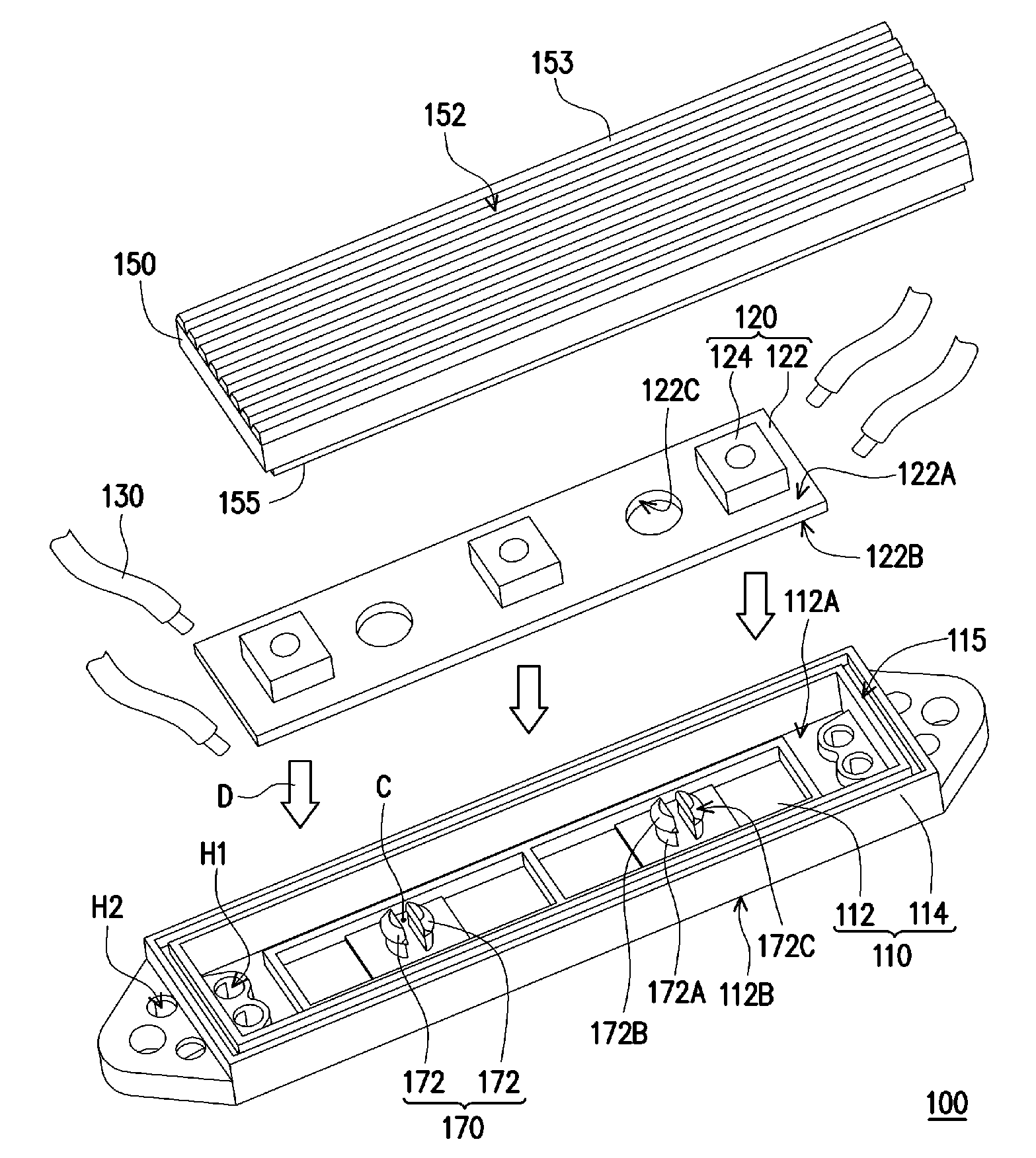
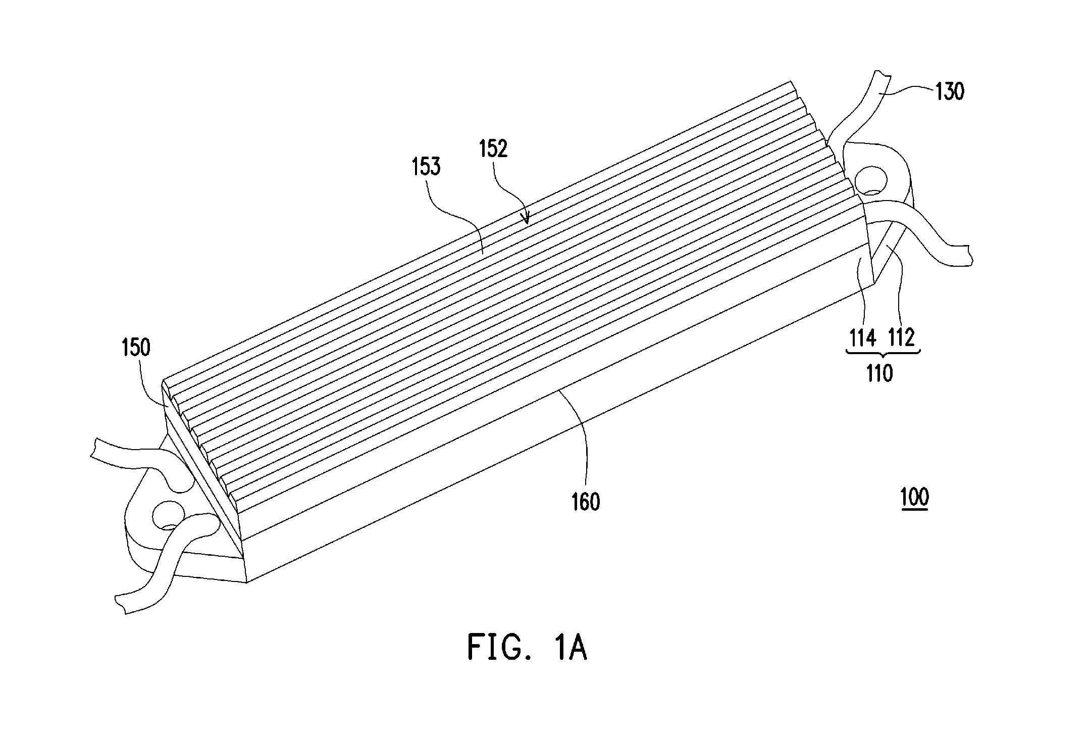
[0036]FIG. 1A is a three-dimensional view of a lighting apparatus according to one embodiment of the present invention, FIG. 1B is an exploded view of the lighting apparatus of FIG. 1A, FIG. 2A is a three-dimensional view of one end of the base of FIG. 1A before filling the encapsulant, and FIG. 2B is a three-dimensional view of one end of the base in FIG. 1A after filling the encapsulant. Referring to FIGS. 1A, 1B, and 2A, the lighting apparatus 100 according to this embodiment includes a base 110, a light emitting unit 120, and a plurality of conducting wires 130. The base 110 includes a bottom board 112 and a side frame 114. The bottom board 112 has a first surface 112A, a second surface 112B, a p...


PUM


Abstract

A lighting apparatus including a base, a circuit board, a light emitting unit, and a locking element is provided. The circuit board has a first surface and a second surface opposite to the first surface, and includes a through hole communicating the first and second surfaces. The circuit board is carried by the base with the second surface resting on the base. The light-emitting element is disposed on the first surface of the circuit board. The locking element comprises resilient hooks each of which including a resilient support, passing through the through hole with a first end of the resilient support connected to the based, and a hook head, connected to a second end of the resilient support opposite to the first end. The hook head is suitable for hooking the first surface of the circuit board.

Description

CROSS-REFERENCE TO RELATED APPLICATION[0001]This application is a continuation of and claims the priority benefit of U.S. patent application Ser. No. 12 / 608,997, filed on Oct. 29, 2009, which claims the priority benefit of Taiwan Patent Application No. 97141851, filed on Oct. 30, 2008. The entirety of the above-mentioned patent applications are hereby incorporated by reference and made a part of this specification.BACKGROUND[0002]1. Technical Field[0003]The present invention relates to a lighting apparatus.[0004]2. Description of Related Art[0005]Along with the advancement of semiconductor technology, light-emitting diodes (LEDs) have achieved a higher power, emitted stronger light. Moreover, the LEDs feature various advantages, such as power saving, long service life, environmental protection, quick start-up, and small volume. Therefore, the LEDs are applied in more and more fields, such as illumination, traffic lights, displays, optical mice, and LED string lamps.[0006]Currently, ...

Claims


Application Information

Patent Timeline
Patent Type & Authority Applications(United States)
IPC IPC(8): F21V5/00F21V21/00
CPCF21S4/003F21V5/02F21Y2101/02F21V19/004F21V31/04F21V15/01F21S4/20F21Y2115/10
Inventor CHIANG, JEN-TALIANG, CHIA-HAO
Owner EVERLIGHT ELECTRONICS
Features
  • R&D
  • Intellectual Property
  • Life Sciences
  • Materials
  • Tech Scout
  • Unparalleled Data Quality
  • Higher Quality Content
  • 60% Fewer Hallucinations
Learn More