

Signal processing apparatus for optical disc and method thereof
a technology of signal processing and optical disc, which is applied in the direction of digital signal error detection/correction, recording signal processing, instruments, etc., can solve the problems of difficult to distinguish which region of te signal is reflected from, and the mechanism has some disadvantages
- Summary
- Abstract
- Description
- Claims
- Application Information
AI Technical Summary
Benefits of technology
Problems solved by technology
Method used
Image



Examples
first embodiment
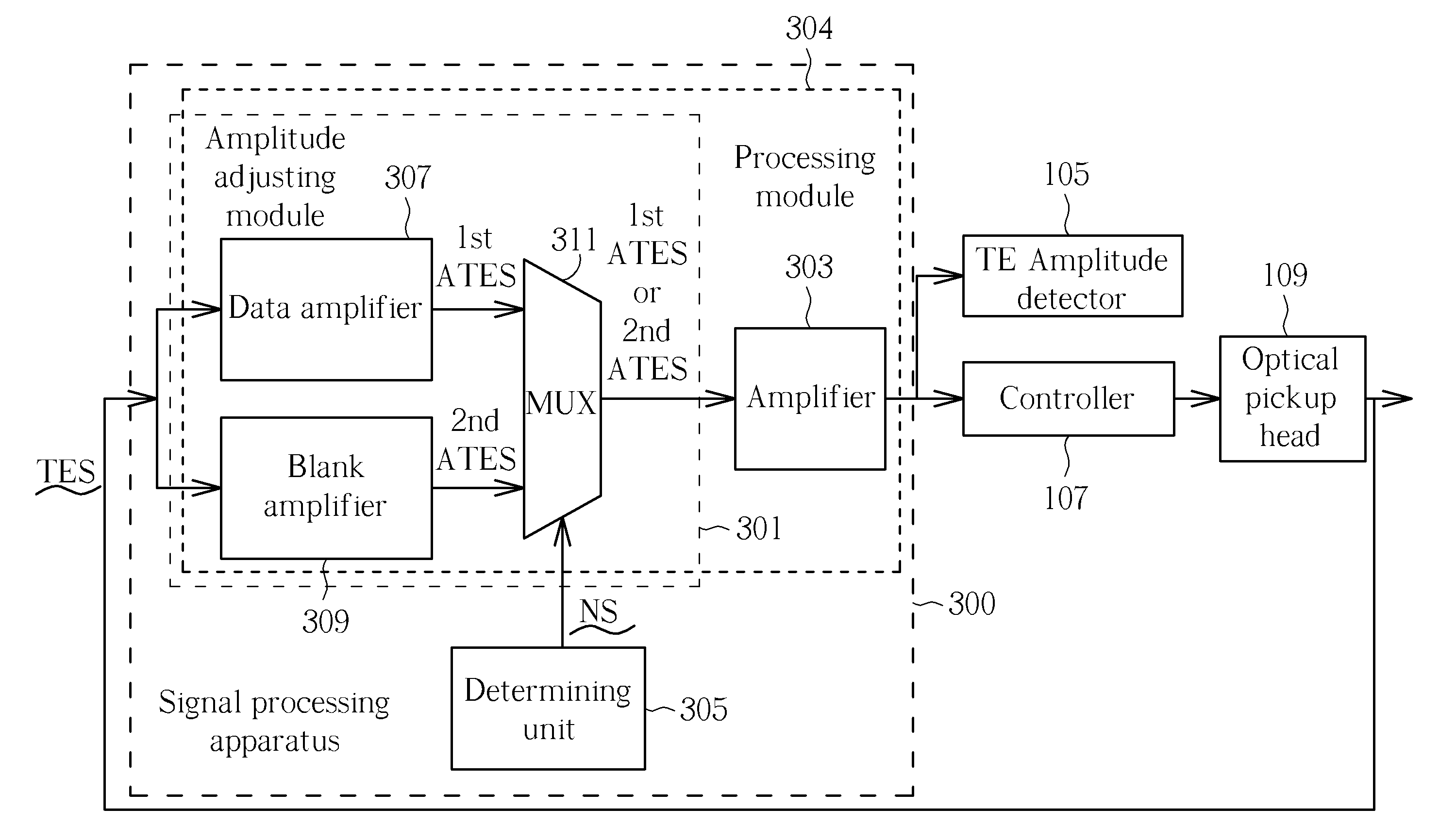
[0025]FIG. 3 is a block diagram illustrating a signal processing apparatus 300 according to the present invention. As shown in FIG. 3, the signal processing apparatus 300 includes an amplitude adjusting module 301, an amplifier 303, and a determining unit 305. Please note that the amplitude adjusting module 301 and the amplifier 303 can be regarded as a processing module 304. The amplitude adjusting module 301 is arranged to amplify a TE signal TES (i.e. an input signal) from the optical pickup head 109 to generate a first amplified TE signal “1st ATES” according to a data amplifying gain. The amplitude adjusting module 301 is also arranged to amplify the TE signal TES to generate a second amplified TE signal “2nd ATES” according to a blank amplifying gain. Since the 1st and 2nd ATES respectively correspond to the data region and the blank region, and the reflection of the data region is smaller than that of the blank region, the data amplifying gain is larger than the blank amplify...
second embodiment
[0039]FIG. 6 is a block diagram illustrating a signal processing apparatus 600 according to the present invention. As shown in FIG. 6, the signal processing apparatus 600 includes an amplifier 601, an amplitude adjusting module 603, and a determining unit 605. The amplifier 601 is arranged to amplify a TE signal TES generated from an optical pickup head 109 to generate an amplified TE signal ATES. The amplitude adjusting module 603 is arranged to adjust amplitude of the amplified TE signal ATES to generate a first output signal 1st OUS according to a data servo amplifying gain, and for adjusting amplitude of the amplified TE signal TES to generate a second output signal 2nd OUS according to a blank servo amplifying gain.
[0040]In this embodiment, the data servo amplifying gain is larger than the blank servo amplifying gain, thus the first output signal 1st OUS and the second output signal 2nd OUS are adjusted to approximately have identical amplitude. The determining unit 605 has a s...
third embodiment
[0053]FIG. 8 is a block diagram illustrating a signal processing apparatus 800 according to the present invention. As shown in FIG. 8, the signal processing apparatus 800 includes a determining unit 801 and a detecting module 803. As mentioned above, the determining unit 801 is arranged to determine that the TE signal TES is derived from the data region or the blank region (i.e. the TE signal TES after processed by the amplifier 809 and the servo adjusting module 811 becomes a signal SD in this embodiment, and the determining unit 801 is arranged to control the signal SD for outputting). The detecting module 803 includes a first loop 805 and a second loop 807. The first loop 805 is arranged to detect an amplitude of the signal to be detected when the determining unit 801 determines that the signal SD to be detected belongs to the data region. The second loop 807 is arranged to detect an amplitude of the signal to be detected when the determining unit 801 determines that the signal b...
PUM
| Property | Measurement | Unit |
|---|---|---|
| reflectivity | aaaaa | aaaaa |
| length | aaaaa | aaaaa |
| reflection | aaaaa | aaaaa |
Abstract
Description
Claims
Application Information