
Information recording and reproducing apparatus, signal decoding circuit, and information recording medium and method

a signal decoding circuit and information recording technology, applied in the field of information recording and reproducing apparatus, signal decoding circuit, information recording medium and method, can solve the problems of data not normally demodulated, decision result y in the decoder is also likely to become an error, and data is not normally demodulated. , to achieve the effect of improving decoding performan

Inactive Publication Date: 2006-09-19
TOSHIBA STORAGE DEVICE CORP
View PDF9 Cites 11 Cited by
  • Summary
  • Abstract
  • Description
  • Claims
  • Application Information

AI Technical Summary

Benefits of technology

[0010]According to the invention, there are provided an information recording and reproducing apparatus, a signal decoding circuit, and information recording medium and method, in which stable clock extraction and amplitude correction are enabled against a deterioration of an S / N ratio of a signal without using an RLL code, thereby improving decoding performance.
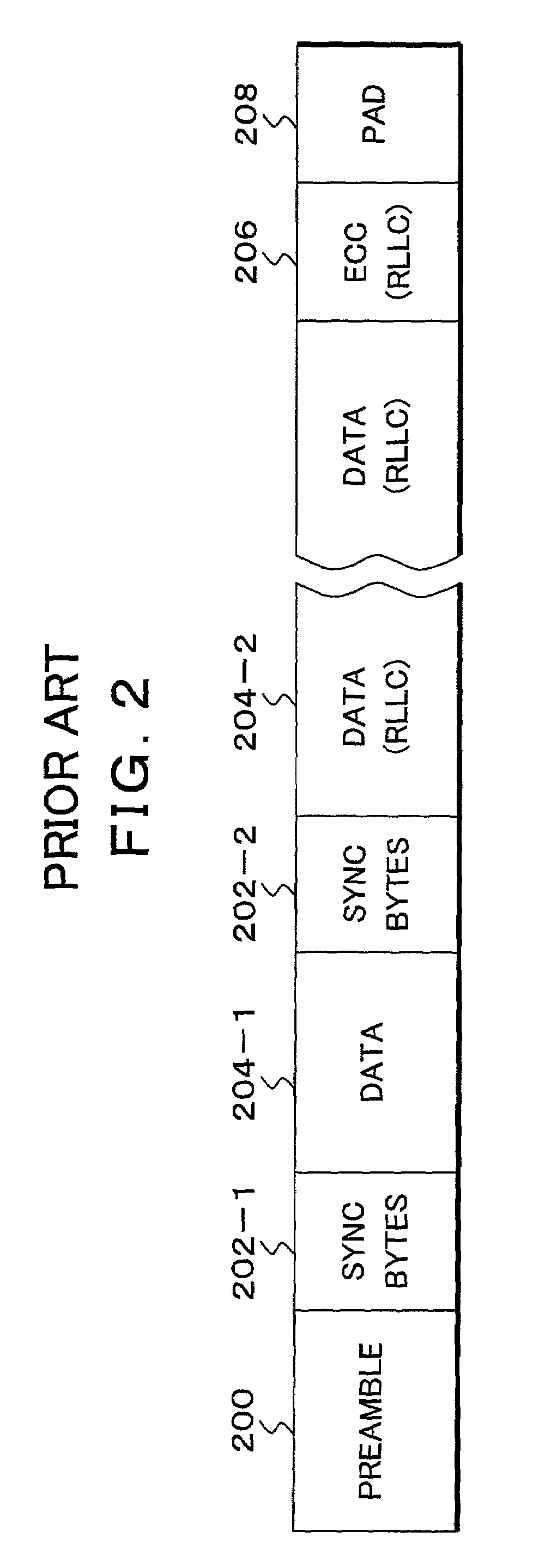
[0011]According to the invention, there is provided an information recording and reproducing apparatus for recording and reproducing information onto / from a magnetic recording medium, comprising: a data recording unit which inserts revise bytes as a predetermined specific code train into at least two or more portions including head and last portions of data and records the data onto the medium upon data recording; and a data reproducing unit which separates a head reproduced signal by using clocks and, thereafter, executes a clock extraction and an amplitude correction by using a signal corresponding to the revise bytes as a specific code train upon data reproduction. Further, the data recording unit and the data reproducing unit record and reproduce user data onto / from the medium without encoding it to an RLL code. As mentioned above, according to the invention, in principle, the RLL code for clock extraction and gain tracking is eliminated, in place of it, revise bytes comprising a specific code train is inserted into the data, and the resultant data is recorded onto the medium. Since the revise bytes are a well-known data train, a decision value Y does not become an error. Even when an S / N ratio of a reproduced signal is low, the stable clock extraction and amplitude correction can be performed. Since the apparatus does not have an RLL decoder, error propagation due to the RLL decoding can be eliminated and the inherent ECC correcting ability can be made the most of.
[0012]In the clock extraction by the data reproducing unit, an inherent sampling time T is obtained on the basis of phase information extracted from the signal corresponding to the specific code train, and the signal amplitude synchronized with the clock is sampled again by an interpolating operation of an interpolating filter according to the sampling time T. The data recording unit arranges sync bytes to the head position of each data which was split by the specific code train and records the data onto the medium. The data reproducing unit detects sync bytes subsequent to the specific code train, presumes a head bit of the data, and obtains a synchronization of the ECC decoding. The data recording unit inserts sync bytes into the specific code train and records the data onto the medium. The data reproducing unit detects the sync bytes from the specific code train, presumes a head bit of the data, and obtains a synchronization of the decoding. By embedding the sync bytes into the revise bytes as mentioned above, the sync bytes are distributed and it is possible to cope with deterioration of the reproduced signal in a wider range. The data reproducing unit obtains a signal mean value and a standard deviation and an autocorrelation of noises by using the signal corresponding to the specific code train and uses them in a likelihood calculation of a data decoding. The data recording unit and the data reproducing unit are constructed by a signal processing integrated circuit. The signal processing integrated circuit is installed in a magnetic disk apparatus or an optical disk apparatus.

Problems solved by technology

When the TA occurs, a signal of a large amplitude is inputted and an adverse influence is caused in the AGC circuit and PLL circuit which have been operating stably so far, so that an error is generated in demodulation data.
Therefore, many noise components are multiplexed even to an output of the FIR filter used in the waveform equalization of the read channel, a decision result Y in the decoder is also likely to become an error.
In such a case, the operation of a feedback system of the timing recovery and the amplitude correction becomes unstable and there is a fear such that the data is not normally demodulated.
There is a problem such that such an error propagation remarkably deteriorates an effect of the ECC.

Method used


Image

  • Information recording and reproducing apparatus, signal decoding circuit, and information recording medium and method
  • Information recording and reproducing apparatus, signal decoding circuit, and information recording medium and method
  • Information recording and reproducing apparatus, signal decoding circuit, and information recording medium and method

Examples


Embodiment Construction

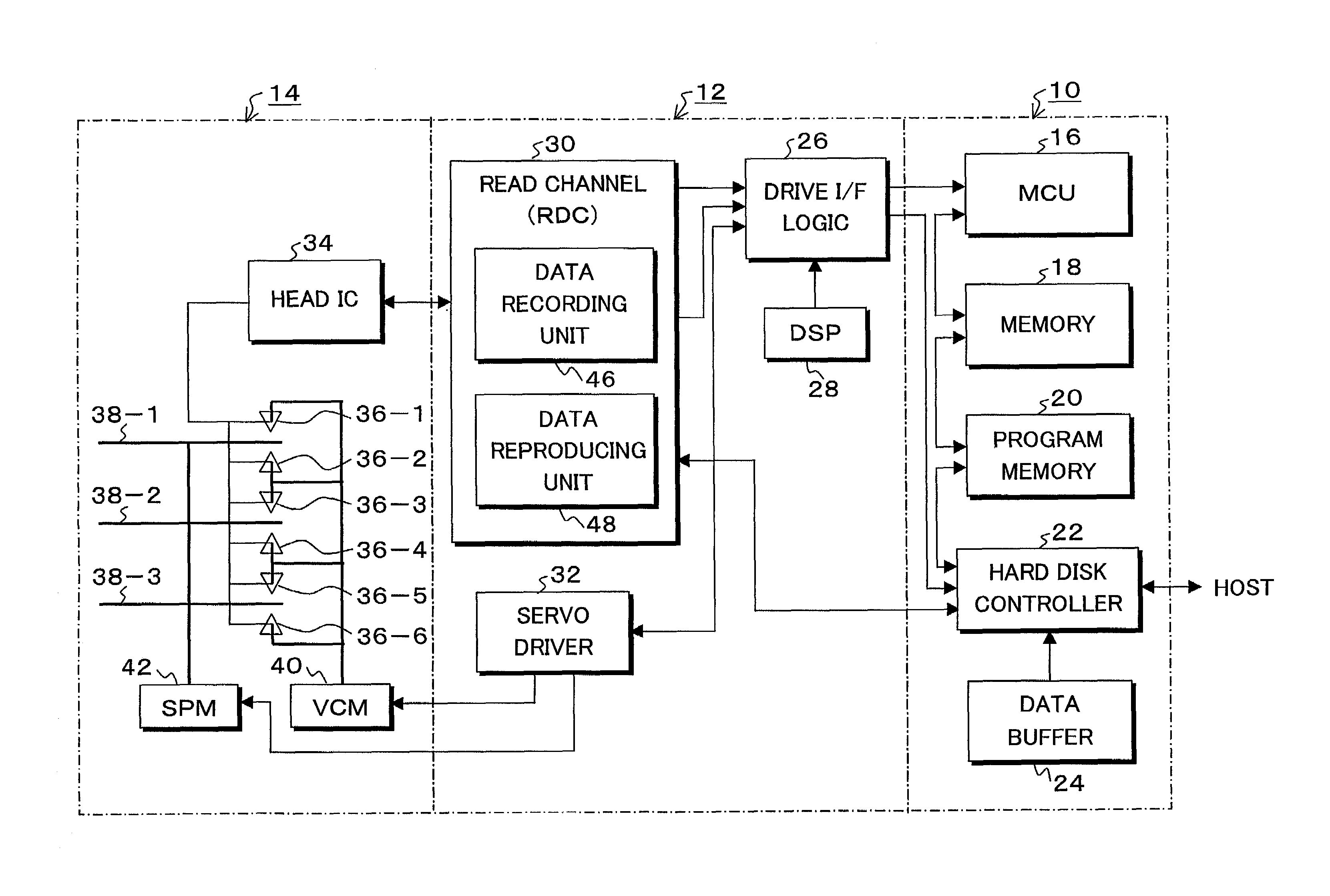
[0034]FIG. 5 is a block diagram of a hard disk drive to which the invention is applied. The hard disk drive comprises an SCSI controller 10, a drive control 12, and a disk enclosure 14. An interface with a host is not limited to the SCSI controller 10 but another proper interface controller can be used. The SCSI controller 10 has: an MCU (main control unit) 16; a memory 18 using a DRAM or an SRAM which is used as a control memory; a program memory 20 using a non-volatile memory such as a flash memory or the like for storing a control program; a hard disk controller (HDC) 22; and a data buffer 24. The drive control 12 has: a drive interface logic 26; a DSP 28; a read channel (RDC) 30; and a servo driver 32. A head IC 34 is further provided for the disk enclosure 14. Combination heads 36-1 to 36-6 each having a recording head and a reproducing head are connected to the head IC 34. The combination heads 36-1 to 36-6 are provided for recording surfaces of magnetic disks 38-1 to 38-3, re...


PUM

PropertyMeasurementUnit
frequencyaaaaaaaaaa
areaaaaaaaaaaa
lengthaaaaaaaaaa

Abstract

Upon data recording, a data recording unit inserts revise bytes as a predetermined specific code train into at least two or more portions including the head and last portions of data and records the data onto a medium. Upon data reproduction, a data reproducing unit separates a head reproduced signal by using clocks and, thereafter, executes a clock extraction and an amplitude correction by using a signal corresponding to the revise bytes as a specific code train. In principle, an RLL code for the clock extraction and gain tracking is eliminated and, in place of the RLL code, the revise bytes comprising the specific code train are inserted into the data and the data is recorded onto the medium.

Description

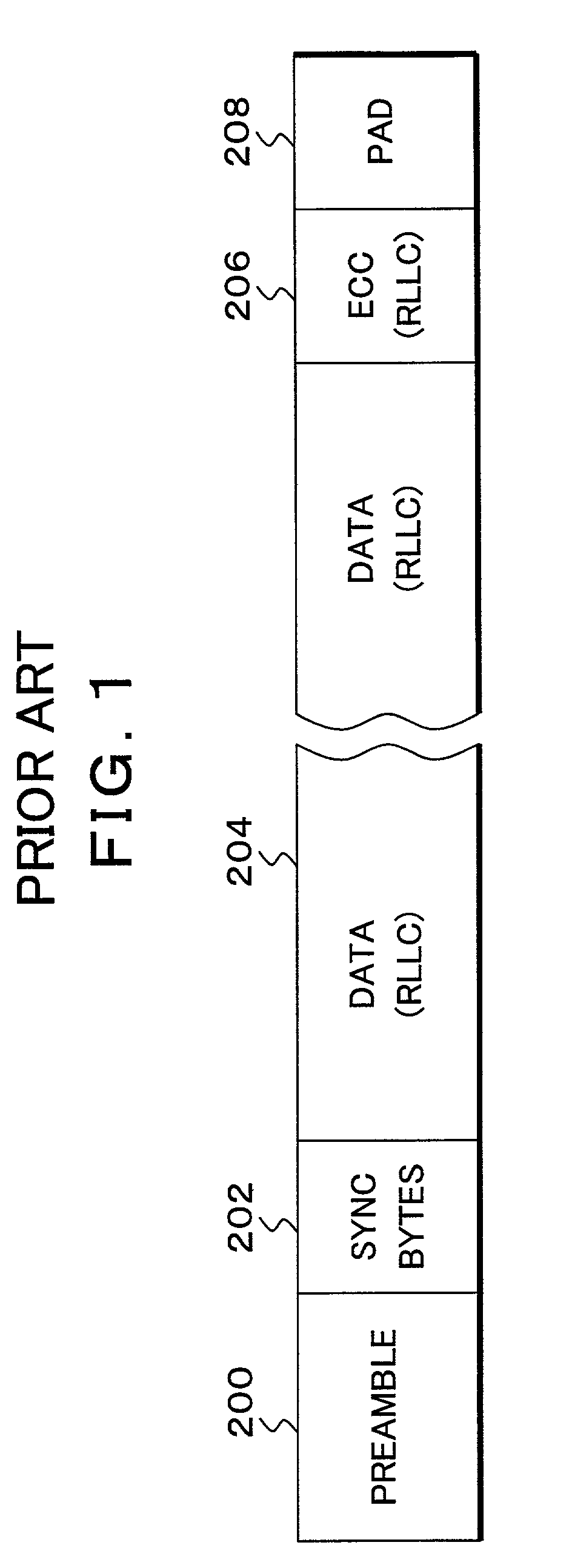
BACKGROUND OF THE INVENTION[0001]1. Field of the Invention[0002]The invention relates to an information recording and reproducing apparatus of a magnetic disk, an MO, an optical disk, a magnetic tape device, or the like and to a signal decoding circuit and information recording medium and method. More particularly, the invention relates to an information recording and reproducing apparatus for sampling a head reproduced signal by an asynchronous dock and, thereafter, performing a timing recovery and a gain control and to a signal decoding circuit and information recording medium and method.[0003]2. Description of the Related Arts[0004]FIG. 1 shows an example of a sector format in a conventional magnetic disk apparatus, and it is constructed by a preamble part 200, sync bytes 202, data 204, an ECC 206, and a pad 208. That is, a specific code train called a preamble part 200 is recorded at the head in the sector format. Upon reproduction, acquisition of a phase and a frequency of a ti...

Claims


Application Information

Patent Timeline
Patent Type & Authority Patents(United States)
IPC IPC(8): G11B5/09G11B5/012G11B20/10G11B7/00G11B20/14H04L7/027
CPCG11B5/012G11B20/1426G11B7/00
Inventor SUGAWARA, TAKAOICHIHARA, KAZUHITO
Owner TOSHIBA STORAGE DEVICE CORP
Learn More