
Tomography imaging apparatus

a technology of tomography and imaging apparatus, which is applied in the direction of instruments, catheters, diagnostic recording/measuring, etc., can solve the problems of large size, complicated apparatus, and inability to accurately detect amplitude, and achieve the effect of accurately detecting the amplitude of an interference signal

Active Publication Date: 2008-03-25
KK TOPCON
View PDF5 Cites 11 Cited by
  • Summary
  • Abstract
  • Description
  • Claims
  • Application Information

AI Technical Summary

Benefits of technology

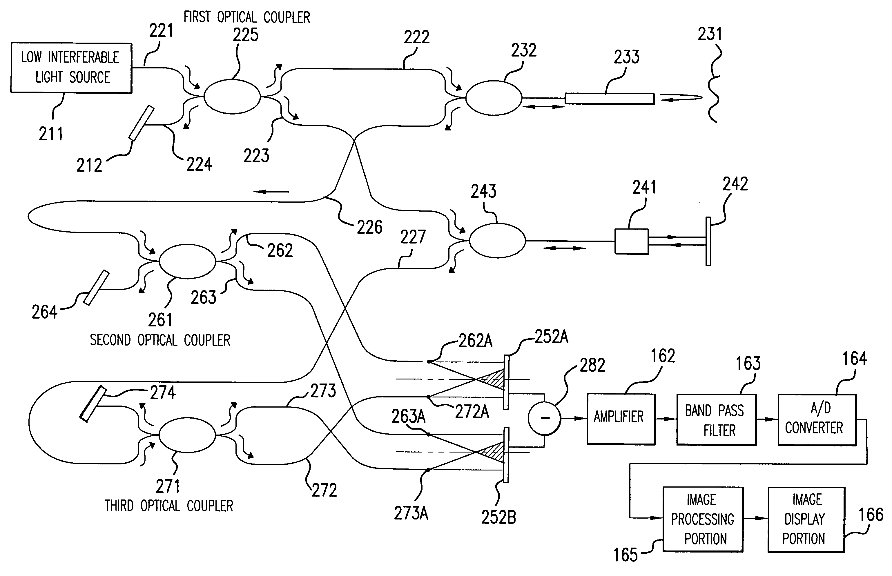
[0019]The invention has been carried out in view of the above-described situation and it is an object thereof to provide a tomography imaging apparatus dispensing with a drive mechanism for moving a reference mirror and capable of accurately detecting an amplitude of an interference signal while a constitution thereof is extremely simple.

Problems solved by technology

Such an OCT technology is referred to as TDOCT (Time Domain OCT) in which a drive mechanism of repeatedly moving the reference mirror in the optical axis direction is needed and the apparatus is large-sized and complicated.
However, according to the above-described technology described in JP-A-2001-272332, an interference signal representing an optical intensity distribution of interfered light provided by the optical detector is multiplied by a cosine function constituting a variable by a phase difference Δ1 of signal light and the reference light as a weight and therefore, an amplitude cannot accurately be detected when an angle θ of the function becomes π / 2, 3π / 2 or the like.

Method used


Image

  • Tomography imaging apparatus
  • Tomography imaging apparatus
  • Tomography imaging apparatus

Examples


Embodiment Construction

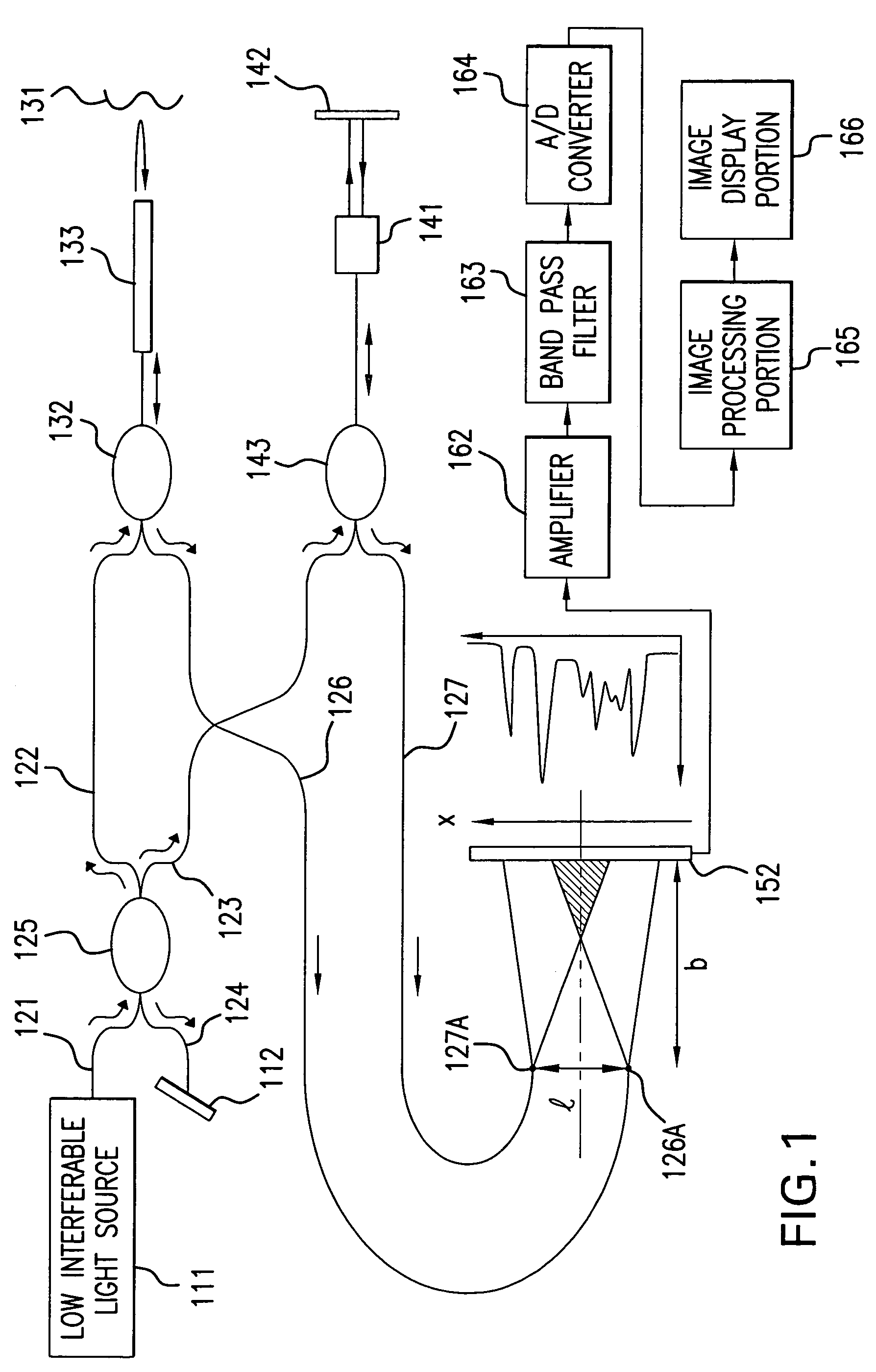
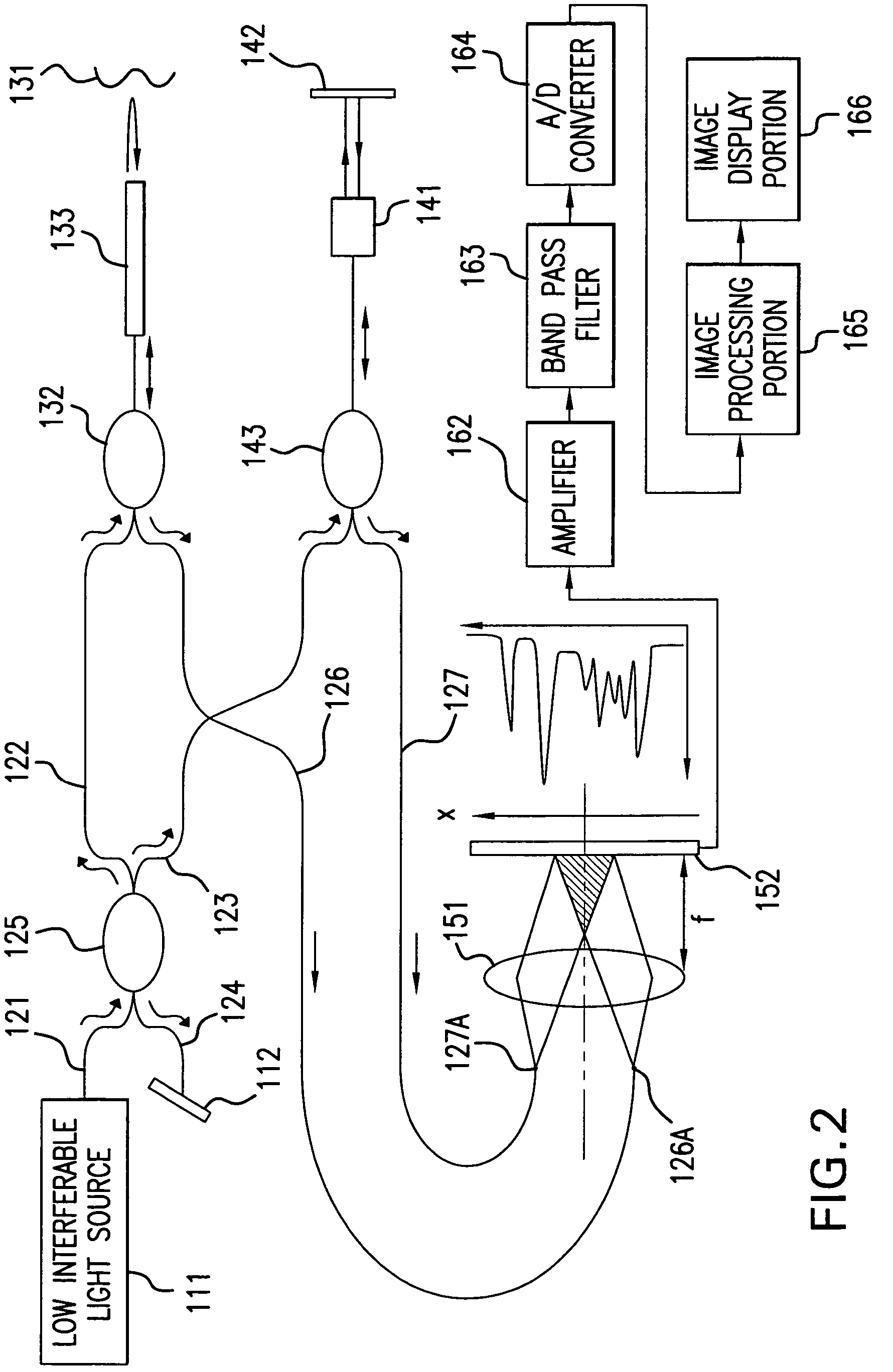
[0047]A tomography imaging apparatus according to an embodiment of the invention will be explained in reference to the drawings as follows.

[0048]FIG. 1 is an outline view showing a tomography imaging apparatus according to a first embodiment of the invention.

[0049]The tomography imaging apparatus according to the embodiment is applied to an endoscope for medical use and comprises a light source portion, an interferometer apparatus portion and a signal processing portion.

[0050]The light source portion comprises a low interferable light source 111. Further, the interferometer apparatus portion comprises a light irradiation optical system portion, guiding portions of signal light and reference light, and a Young's interferometer portion to constitute a Michelson interferometer apparatus of a so-to-speak unbalance type as a whole. The light irradiation optical system portion comprises four optical fibers 121, 122, 123, 124 and an optical coupler (2×2 coupler) 125, a first and a second o...


PUM

PropertyMeasurementUnit
core diametersaaaaaaaaaa
tomography imagingaaaaaaaaaa
phase shiftaaaaaaaaaa

Abstract

A tomography imaging apparatus comprises: a light source that emits light having a low interferable performance; a light irradiation optical system constituted to split the light emitted from the light source into two, irradiate one of the split light to a subject and irradiate the other one of the split light to a reference mirror; a first guiding member that guides signal light to a first light emitting end, the signal light being from the subject based on light irradiation from the light irradiation optical system; a second light guiding member that guides reference light to a second light emitting end, the reference light being from the reference mirror based on the light irradiation; and a multipixel image taking element that provides an optical intensity distribution of interfered light by the signal light emitted from the first light emitting end and the reference light emitted from the second light emitting end.

Description

RELATED APPLICATIONS[0001]This application claims the priority of Japanese Patent Application No. 2004-175401, filed on Jun. 14, 2004, which is incorporated herein by reference.BACKGROUND OF THE INVENTION[0002]1. Field of the Invention[0003]The present invention relates to a tomography imaging apparatus used when a tomographic image of a subject is provided in medical or industrial field by applying a method by Optical Coherence Tomography (hereinafter, referred to as OCT) constituted by combining a light source for outputting light having a short coherence length and an equal light pass length interferometer of a Michelson interferometer or the like, particularly relates to a tomography imaging apparatus which does not need a reference face scanning mechanism for providing image data in a depth direction of a subject.[0004]2. Description of the Related Art[0005]In recent years, in a field of taking an image of a subject for medical use or industrial use, particularly in a field of ...

Claims


Application Information

Patent Timeline
Patent Type & Authority Patents(United States)
IPC IPC(8): G01T1/166G01B9/02A61B10/00G01N21/17H01J3/14
CPCA61B5/0066A61B5/6852G01B9/02091G01B9/02032G01N21/4795
Inventor FUJITA, HIROSHI
Owner KK TOPCON
Learn More