Eureka AIR delivers breakthrough ideas for toughest innovation challenges, trusted by R&D personnel around the world.

Device to release a self-expanding implant

Active Publication Date: 2012-06-07
CR BARD INC
View PDF4 Cites 27 Cited by
  • Summary
  • Abstract
  • Description
  • Claims
  • Application Information

AI Technical Summary

Benefits of technology

[0011]It is preferred to use as the material of the rolling membrane a cold-drawn polyethylene terephthalate material. For teaching of the use of such material, reference is made to the earlier WO disclosures of the present application, noted above. There is in fact a happy conjunction of material properties, between the cold-drawn PET material and the technical features of the present invention, for the anisotropic molecular lattice of the drawn material facilitates the operation of the slitter.
[0013]Thinking again about friction forces, in a system without the slitter, one can imagine that any sort of impediment to the proximal movement of the outer sleeve will result in greater levels of longitudinal stress in the outer sleeve of the rolling membrane proximal of the impediment. Such stresses will have a tendency to reduce the diameter of the outer sleeve under tension. Any such “necking in” of the outer sleeve will, self-evidently, increase forces of friction between the luminal surface of the outer sleeve, sliding over the abluminal surface of the inner sleeve. One can readily imagine that, if the situation worsens, then the system can “bind up”, preventing any further proximal movement of the rolling edge and frustrating the ability of the doctor to release the implant any further, possibly resulting in breakage of any component of the catheter delivery system that is in tension for releasing the implant, and risk to the patient. With the slitter of the present invention, however, the likelihood of such “binding up” is reduced.
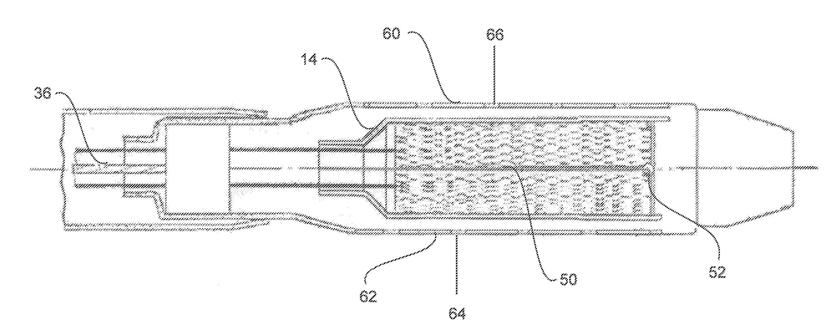
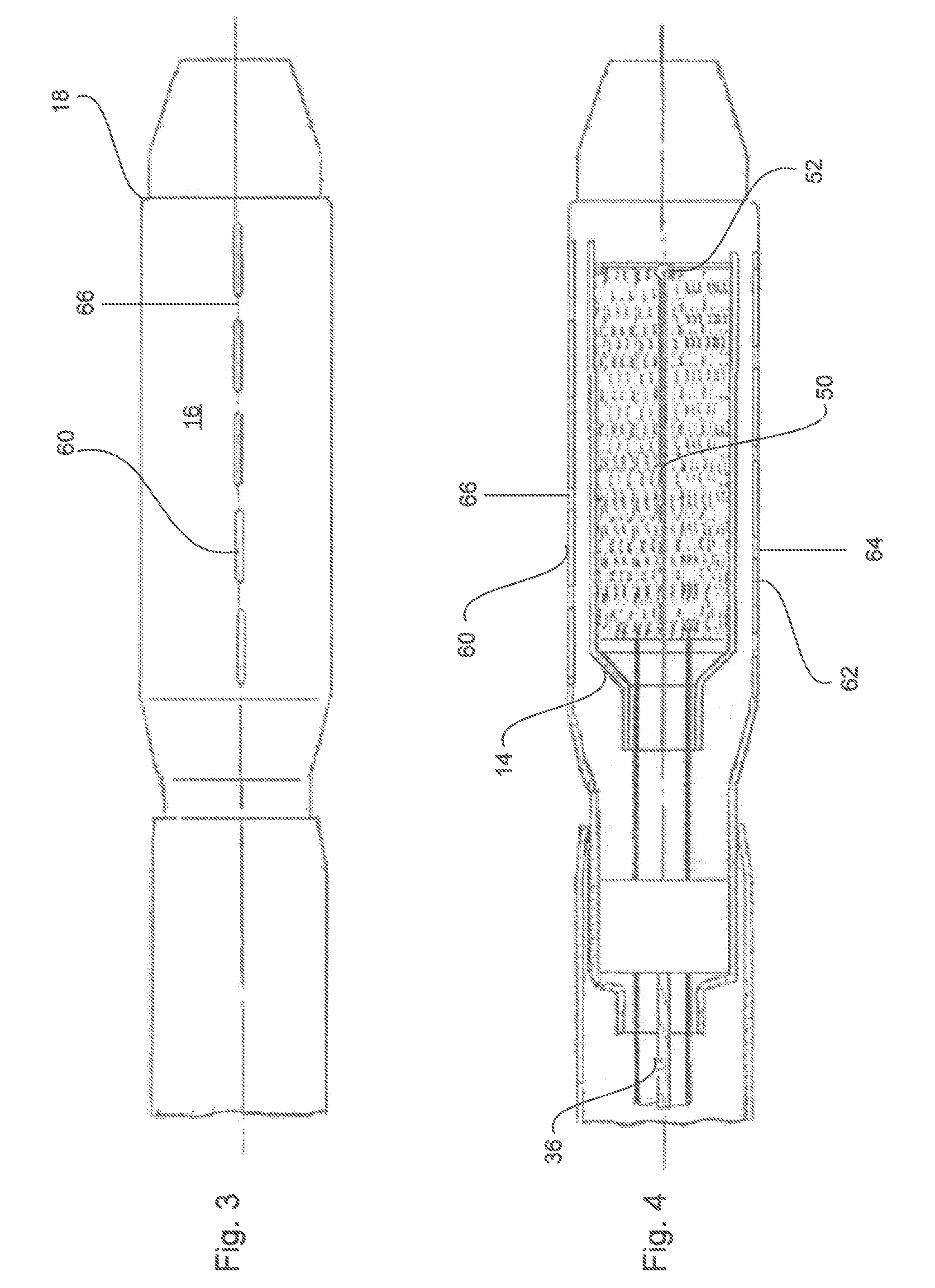
[0014]Further improvements in the smoothness and reliability of stent release are accomplished by providing the outer sleeve with a plurality of slits that go through the wall thickness of the outer sleeve and allow that outer sleeve to “breathe” radially in and out, as it is pulled proximally down the length of the implant bed, during release of the implant. If one supposes that the implant includes features such as radiopaque markers or membrane coatings, that can give rise to local variations of implant diameter, then an ability in the outer sleeve to “breathe” radially in and out as it slides proximally over these diameter variations, will reduce the likelihood of the binding of the proximally retreating outer sleeve on the structure radially inside it, during implant release.
[0015]Judicious design of the slits can accomplish the objective of breathability of the proximally retreating outer sleeve, without total loss of the hoop stress in the outer sleeve that will contribute to radial restraint of the radially compressed implant, prior to its release. Note, however, that the slits need not be provided in the inner sleeve and that the hoop stress in the inner sleeve, alone, can be sufficient to constrain the stent until the moment of its release. The presently preferred arrangement of through slits is to provide two or more sets of such slits, each set being a plurality of the slits, co-linear, and with each slit having a length less than 20% of the length of the implant bed, and with the slits regularly spaced from each other by a spacing that is comparable with the length of each slit, but somewhat less than the length of each slit. In the embodiment illustrated below, there are just two such sets of slits, spaced 180° apart from each other around the circumference of the implant bed, and with the slits of one set staggered along the length of the sleeve, relative to the slits of the other set. However, three or more sets of slits can be provided, where the sets of slits are similarly evenly spaced apart in the circumferential direction and staggered.

Problems solved by technology

With self-expanding stents of ever-greater radial force, confined within a rolling membrane of ever-smaller wall thickness, there is an increasing potential for rupture of the membrane and premature release of the implant, so the rolling membrane sleeve system must be carefully designed to frustrate that possibility.

Method used


Image

  • Device to release a self-expanding implant
  • Device to release a self-expanding implant
  • Device to release a self-expanding implant

Examples


Embodiment Construction

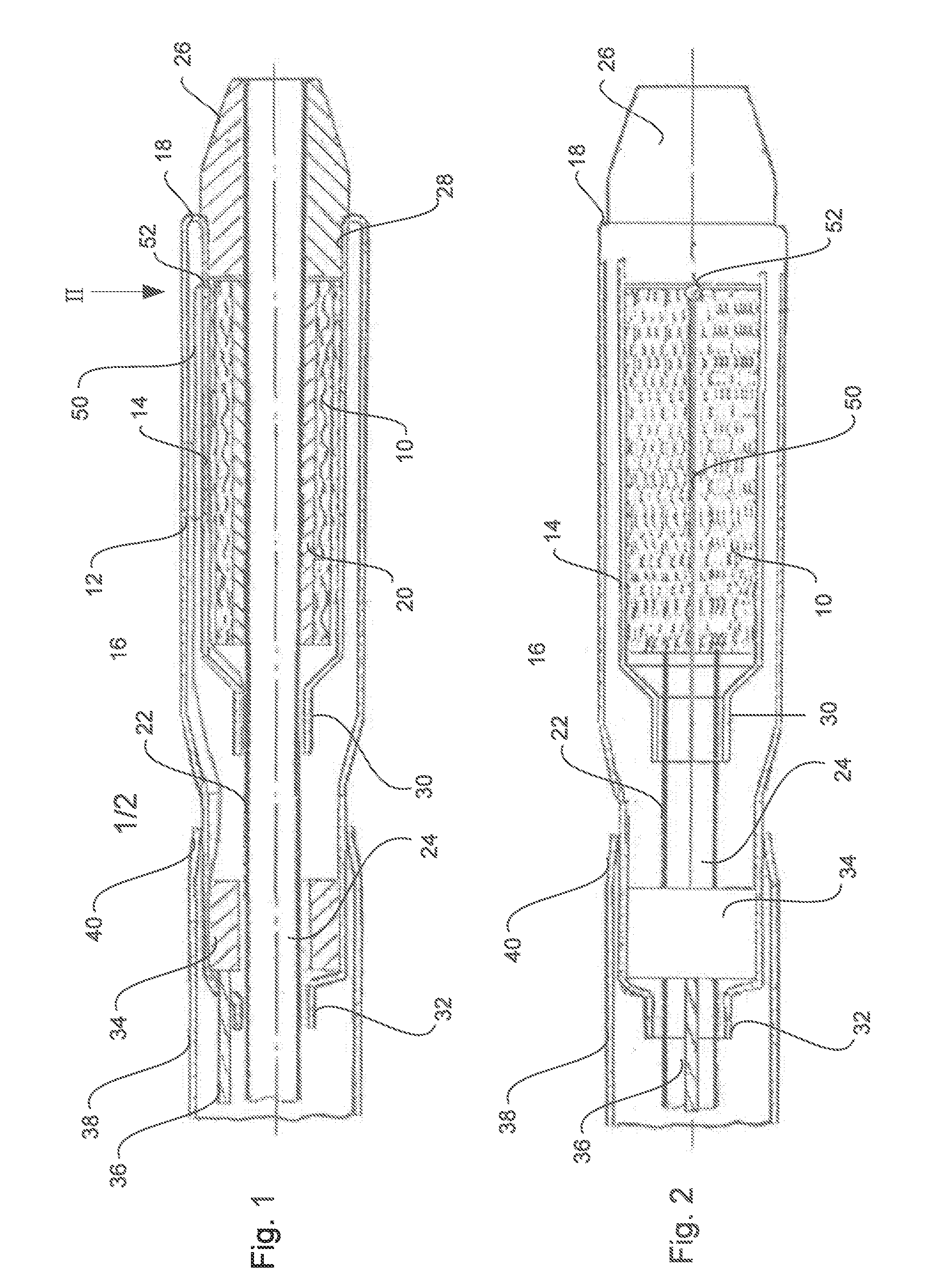
[0021]Looking first at FIG. 1 we see a self-expanding stent 10 radially confined within a rolling membrane 12 which features an inner sleeve 14, an outer sleeve 16 and a rolling edge 18 distal of the bed 20 that receives the stent 10. The bed 20 is on a shaft 22 that defines a guidewire lumen 24 and carries an atraumatic tip 26 that has a rebate 28 to receive the distal end of the rolling membrane 12 and the rolling edge 18.

[0022]At the proximal end of the inner sleeve 14, the rolling membrane 12 is secured at an annulus 30 to the shaft 22. The other end of the rolling membrane 12 extends along the shaft proximally until its end 32 is proximal of a collar 34 that is freely slidable on the abluminal surface of the shaft 22. The membrane 12 is secured to the abluminal surface of the collar 34. The collar 34 is on the distal end of a pull wire 36 that runs all the way to the proximal end of the catheter delivery system of which the distal end is shown in FIG. 1. The reader will appreci...


PUM


Abstract

A device to release from an implant bed in the device a self-expanding implant by pulling back proximally, the length of the implant, a rolling membrane with an inner sleeve that extends distally to the distal end of the implant and an outer sleeve that extends proximally, from the distal end of the inner sleeve, the outer sleeve, during said release, pulling the distal end of the inner sleeve back proximally over the abluminal surface of the remainder of the inner sleeve, proximal of its distal end, the device having a slitter, that is caused to move proximally contemporaneously with the outer sleeve, to slit the inner sleeve progressively, starting at a distal point in the inner sleeve, and progressing proximally along the length of the inner sleeve.

Description

PRIORITY[0001]This application claims priority to U.S. Provisional Application No. 61 / 418,657, filed Dec. 1, 2010, and to United Kingdom Patent Application No. 1020373.5, filed Dec. 1, 2010, each of which is incorporated by reference in its entirety into this application.TECHNICAL FIELD[0002]This invention relates to a device to release from an implant bed in the device a self-expanding implant by pulling back proximally, the length of the implant, a rolling membrane with an inner sleeve that extends distally to the distal end of the implant bed and an outer sleeve that extends proximally, from the distal end of the inner sleeve, the outer sleeve, during said release, pulling the distal end of the inner sleeve back proximally over the abluminal surface of the remainder of the inner sleeve, proximal of its distal end.[0003]Such devices are disclosed in Applicant's earlier WO2010 / 076052 and WO2010 / 076057. Other devices that use a rolling membrane are disclosed in, for example, Scimed ...

Claims


Application Information

Patent Timeline
IPC IPC(8): A61F2/84A61F2/966
CPCA61F2002/9665A61F2/966A61F2/97
Inventor DORN, JURGENDIETRICH, DANIEL
Owner CR BARD INC
Why Eureka
Eureka Blog
Learn More