Floating slab and its floating track bed

A floating track bed and floating slab technology, applied in the field of rail transit, can solve the problems of restricting large-scale popularization and application, weak resistance to bending moment, restricting the speed of construction, etc., achieving reasonable stress, reasonable vibration characteristics, and improved use. effect of life

Active Publication Date: 2016-04-13
GERB QINGDAO VIBRATION CONTROL +1
View PDF7 Cites 0 Cited by
  • Summary
  • Abstract
  • Description
  • Claims
  • Application Information

AI Technical Summary

Problems solved by technology

The floating slab track bed composed of prefabricated short slabs is connected in this way. At present, the telescopic shear hinge is used, but there are the following problems: Although the telescopic shear hinge can transmit the shear force well, it can prevent the floating ballast bed from collapsing. The difference in vertical and lateral deformation between adjacent prefabricated short slabs is too large, but their ability to resist bending moments is weak, resulting in a strong "seesaw" effect of the prefabricated short slabs when the train passes, that is, the prefabricated short slab ends at the bogie Sinking, the other end is on the rocker, the force of the prefabricated slab body, elastic vibration isolation device and steel rail is relatively large
In order to overcome the "see-saw" effect, some plans have added an elastic vibration isolation device between the ends of the slabs. Although the "see-saw" effect can be overcome to a certain extent, when the entire floating track bed is lifted and leveled, adjustments are added. link, thus restricting the speed of construction, increasing the cost of construction, and objectively restricting the large-scale application of such technologies

Method used


Image

  • Floating slab and its floating track bed
  • Floating slab and its floating track bed
  • Floating slab and its floating track bed

Examples


Embodiment 1

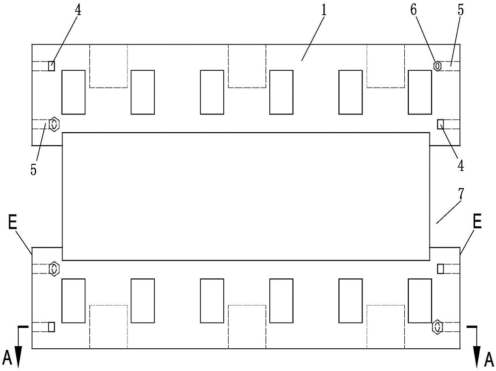
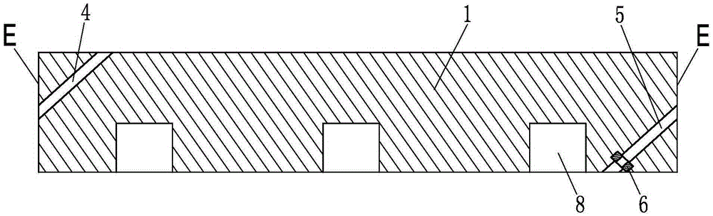
[0047] like figure 1 and figure 2 The floating plate of the present invention as shown includes a floating plate body 1, and observation ports 7 are provided at both ends of the floating plate body 1, and an installation reserved space 8 for matching with an elastic vibration isolation device is provided on the floating plate body 1, The connection ends on both sides of the floating plate body 1 are respectively provided with a first assembly hole 4 and a second assembly hole 5, the transverse vertical end surface at the connection end is the connection mating surface E, the first assembly hole 4 and the second assembly hole The two assembly holes 5 are all arranged in the longitudinal vertical plane of the floating plate body; the first assembly hole 4 runs through the floating plate body 1 obliquely, its upper opening is located on the top surface of the floating plate body 1, and the lower opening is located on the top surface of the floating plate body 1. On the connecti...

Embodiment 2

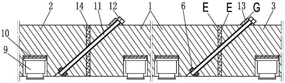
[0063] like Figure 4 , Figure 5 Shown is the floating plate of the present invention, with figure 1 , figure 2 The difference of the floating plate shown is that the floating plate body 1 is provided with a connecting sleeve 17 that cooperates with the elastic vibration isolation device, and each connection end of the floating plate body 1 is respectively provided with three first assembly holes 4 and three A second assembly hole 5, a groove 15 is arranged on the top surface of the floating plate body 1 corresponding to the upper opening of the first assembly hole 4, and the bottom surface of the groove 15 forms a locking shoulder G, which is perpendicular to the locking shoulder G. The central axis of the first assembly hole 4 is set. In addition, the floating plate body 1 is provided with an observation port 2, of course, the observation port 2 is closed by the end cover during use to prevent foreign objects from falling. In addition, the lower opening of the second a...

Embodiment 3

[0069] like Figure 9 Shown is the floating plate of the present invention, with Figure 4 and Figure 5 The difference of the floating plate shown is that the assembly interface in the floating plate body 1 is the articulated shoulder provided at the lower part of the second assembly hole 5, and the articulated shoulder is integrated and fixed in the concrete structure at the lower part of the second assembly hole. Metal articulated plate 20 is formed, and the middle part of articulated retaining shoulder is provided with installation through hole 21, and the outline shape of installation through hole 21 is rectangle; In addition, the connecting end of floating plate body 1 is respectively provided with adjacent floating plate. The anti-displacement structure of limited fit, the anti-displacement structure includes a convex structure or a groove structure, wherein a convex structure composed of a limit pin shaft 22 is provided on one side of the connection end, and a limit p...


PUM


Abstract

The invention belongs to the field of the rail transport, and in particular to track bed slabs and a floating track bed formed by track bed slabs. The floating slab and floating track bed thereof comprise a floating slab body, an installing reserved space or a jointing sleeve matched with an elastic isolation mounting is arranged on the floating slab body, the connecting end of the floating slab body is provided with a first assembly hole and a second assembly hole, and the first assembly hole and the second assembly hole are arranged in the vertical plane of the floating slab body; the first assembly hole is inclined and penetrates through the floating slab body, an opening in the upper portion is arranged on the top face of the floating slab body, and an opening of the lower portion is arranged in the connecting coordinated face of the floating slab body; the second assembly hole is inclined and penetrates through the floating slab body, an opening of the upper portion is arranged in the connecting coordinated face of the floating slab body, the lower portion of the second assembly hole is provided with an assembly connector, and the assembly connector is located on the bottom of the floating slab body. The floating slab has the advantages that the structure is simple, the manufacture is easy, and the use is convenient. By means of the floating track bed formed by connecting the floating slabs, the efficiency of construction is high, the post-maintenance is convenient, the vibration performance is more excellent, the stress is more reasonable, and the service life is longer.

Description

technical field [0001] The invention belongs to the field of rail transportation, and in particular relates to a ballast bed slab and a floating ballast bed formed therefrom. Background technique [0002] With the development of society and the progress of science and technology, the importance of rail transit has become increasingly prominent. In the construction of rail transit, the vibration and noise problems generated during vehicle operation must be solved, otherwise it will seriously affect the quality of life of surrounding residents and endanger the safety of surrounding buildings. At the same time, the stability, safety and service life of rail transit itself will also be affected. affected. In order to control the vibration and noise generated in the operation of rail transit, researchers have developed many vibration and noise reduction products, among which the steel spring floating ballast bed technology is recognized as one of the technologies with the best v...

Claims


Application Information

Patent Timeline
Patent Type & Authority Patents(China)
IPC IPC(8): E01B1/00E01B19/00
CPCE01B1/00E01B19/003E01B2201/04E01B2204/01E01B2204/12
Inventor 尹学军白廷辉葛世平毕湘利陈彬刘加华王建立王建孔祥斐王乾安李维赞刘扬董国宪邢海灵薛松
Owner GERB QINGDAO VIBRATION CONTROL
Why Eureka
Try Eureka