Rope molding jig

a technology of rope molding and jig, which is applied in the field of system and method of manufacturing rope molding, can solve the problems that prior art equipment and methods are unable to economically produce continuous molding sections with helically shaped features, and prior art equipment cannot manufacture long molding sections with helical features

Inactive Publication Date: 2012-06-14
WOODMASTER TOOLS
View PDF7 Cites 3 Cited by
  • Summary
  • Abstract
  • Description
  • Claims
  • Application Information

AI Technical Summary

Benefits of technology

[0009]A second aspect of the present invention concerns a method of shaping an elongated stock. The broadly includes the steps of operating a feed mechanism that is designed to move the stock along a feed axis; orienting the stock so that the stock axis is held at an oblique angle relative to the feed axis, with the feed mechanism thereby causing the stock to simultaneously rotate about the stock axis and move axially along the stock axis; and shaping the stock as the stock is rotated and moved axially.

Problems solved by technology

For instance, prior art equipment and methods are unable to economically produce sections of continuous molding with helically shaped features.
In particular, the prior art equipment cannot manufacture long molding sections with helical features that extend continuously along the length of the molding section.

Method used


Image

  • Rope molding jig
  • Rope molding jig
  • Rope molding jig

Examples


Embodiment Construction

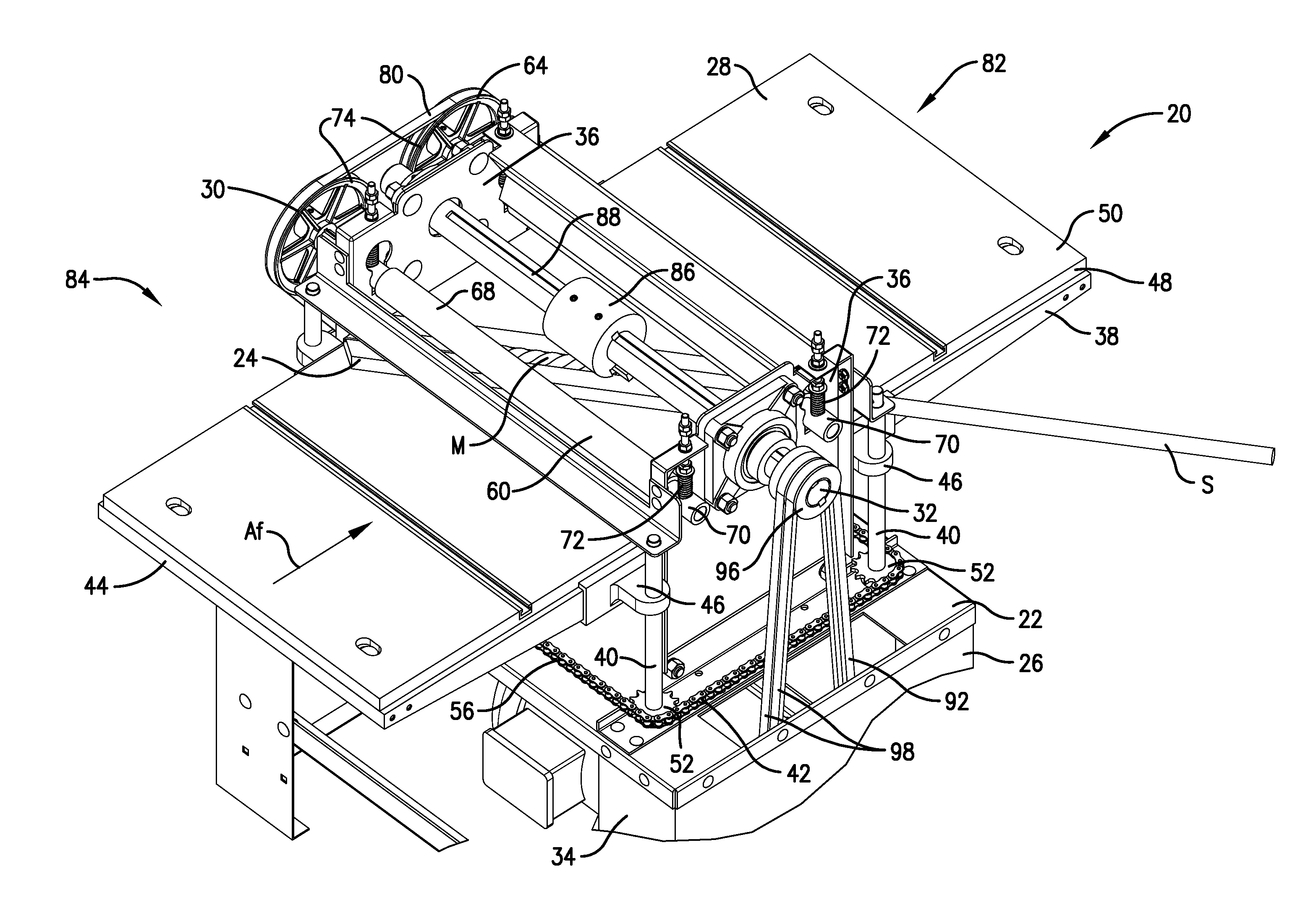
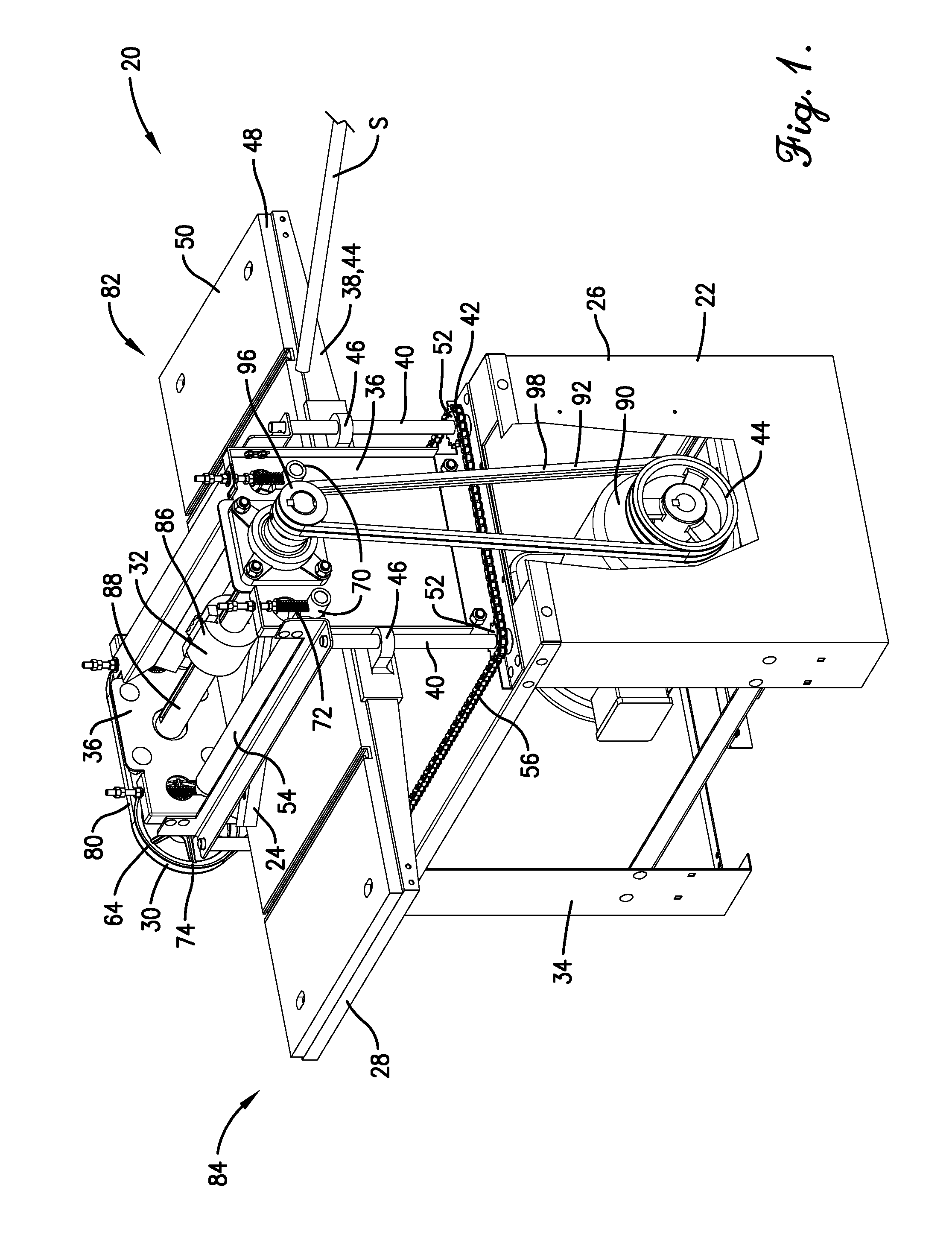
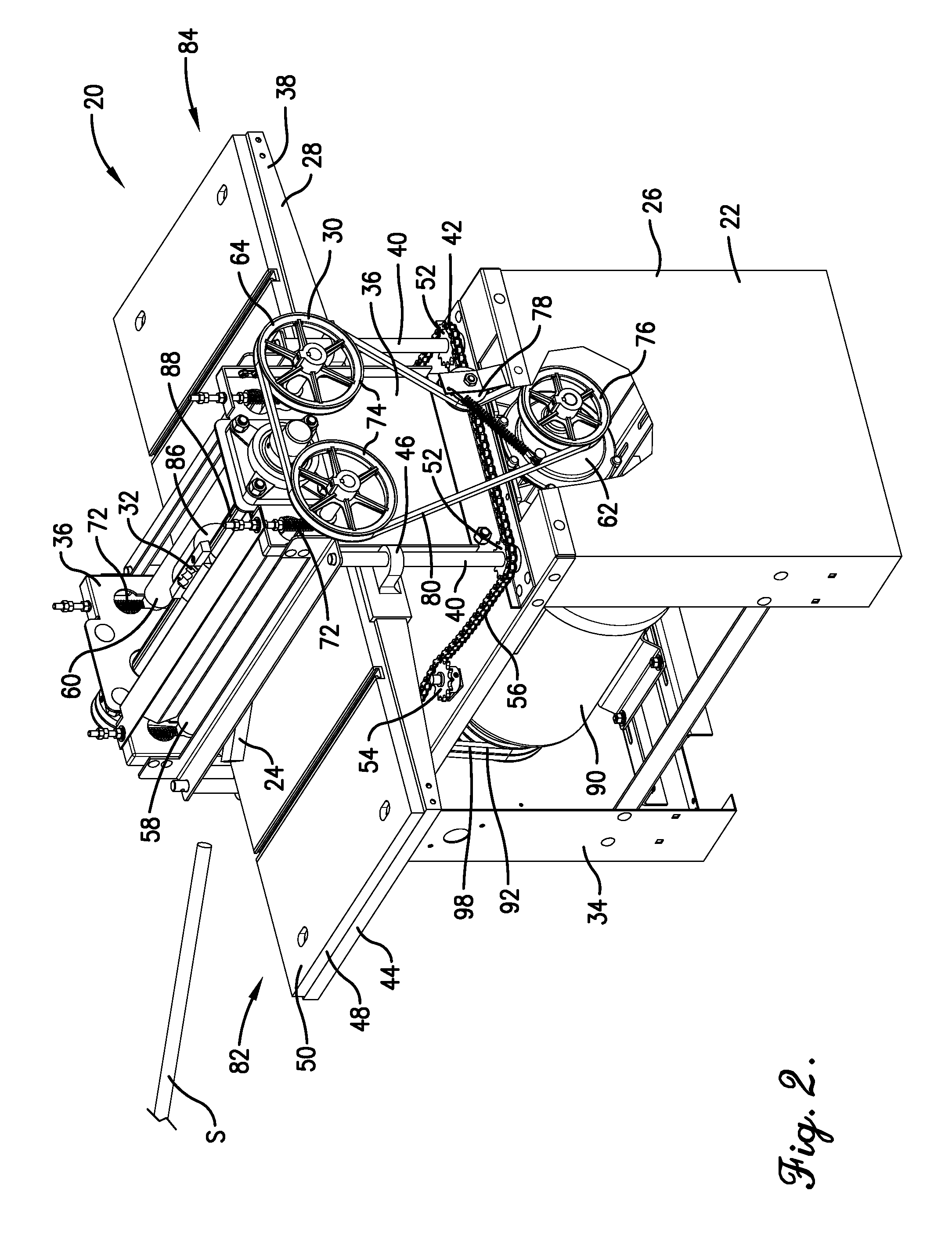
[0024]Turning initially to FIGS. 1 and 2, a wood-shaping system 20 is constructed in accordance with a preferred embodiment of the present invention and is preferably used to produce a continuous molding M from dowel stock S, as will be discussed. The system 20 broadly includes a powered machine 22 and a jig 24.

[0025]Turning to FIGS. 5-8, the illustrated system 20 is preferably configured to form molding M with helical features from dowel stock S. The illustrated molding M preferably has the shape of a continuous rope and includes a pair of continuous twisted strand surfaces St (see FIGS. 6 and 7). Specifically, the strand surfaces St are each defined by a generally convex cross-sectional profile that extends along a helical direction about a stock axis SA (see FIGS. 5 and 8) so as to imitate the general shape of a helically-wound rope strand that is used to form a twisted rope (also referred to as laid rope). The strand surfaces St are shaped to define a pitch distance dimension P,...


PUM


Abstract

A stock-shaping machine is operable to shape elongated stock and includes a powered machine and a jig. The powered machine includes a feed mechanism shiftably mounted relative to a frame so as to feed stock through the machine. The machine also includes a shaping device supported relative to the frame to shape the stock during feeding thereof. The elongated jig orients the stock so that an axis of the stock is at least generally parallel to a jig axis. The jig permits rotation of the stock relative to the jig about the stock axis and longitudinal sliding of the stock along the jig. The jig is mounted with the jig axis at an oblique angle relative to a machine feed axis so that shifting of the feed mechanism causes rotation and longitudinal sliding of the stock.

Description

BACKGROUND[0001]1. Field[0002]The present invention relates generally to equipment used to manufacture molding and similar products. More specifically, embodiments of the present invention concern a system and method of manufacturing rope molding.[0003]2. Discussion of Prior Art[0004]Various types of equipment have been used to manufacture wood moldings. One conventional molding machine includes a table, a rotating cutting head above the table, and a powered feed mechanism. The cutting head has a knife profile that corresponds to the shape of the molding. The feed mechanism urges stock through the machine so that the knife cuts a continuous molding shape that extends linearly along the length of the stock. Additionally, a conventional powered lathe can also be used to produce molding with a shape that varies along the length of the molding.[0005]Conventional molding equipment and methods have certain deficiencies. For instance, prior art equipment and methods are unable to economica...

Claims


Application Information

Patent Timeline
Patent Type & Authority Applications(United States)
IPC IPC(8): B27M3/00B27G13/12
CPCB27C5/06B27C5/08B27C7/005B27M3/12B27G13/12B27M3/08B27C7/06
Inventor CROWDER, MICHAEL ROBERT
Owner WOODMASTER TOOLS
Why Eureka
Try Eureka