
LED lamp capable of adjusting a beam spread thereof

a technology of led lamps and beam spreads, which is applied in the direction of fixed installation, lighting and heating apparatus, lighting support devices, etc., can solve the problems of limited illumination scope of led members, complicated replacement of projecting units, and gaskets placed between casing units and inner covers that may be subject to elastic fatigue, etc., and achieve favorable luminous efficacy

Inactive Publication Date: 2012-06-14
JIAWEI RENEWABLE ENERGY CO LTD
View PDF3 Cites 14 Cited by
  • Summary
  • Abstract
  • Description
  • Claims
  • Application Information

AI Technical Summary

Benefits of technology

[0006]It is therefore the purpose of this invention to provide an LED lamp capable of adjusting a beam spread thereof that allows a beam angle of the projected light to be freely adjusted so as to suitably concentrate or expand a light scope and obtain the favorable luminous efficacy.
[0007]The LED lamp holder capable of adjusting a beam spread thereof in accordance with the present invention comprises a seated body with an accommodating room, a circuit unit as well as a projecting unit respectively disposed within the accommodating room, and a cover unit connected with the seated body. Characterized in that, an adjusting module is disposed between the seated body and the cover unit. The adjusting module has a holder connecting to the seated body, a motivating member penetrating the aperture, an engaging member allowing the motivating member to engage with the holder, and a lens disposed on the engaging member. Wherein, at least three guiding slots are defined around an inner periphery of the holder. At least three open parts are defined on a periphery wall of the motivating member. A plurality of buckling members are extended outward from the peripheral wall for clasping the holder. A plurality of protrudent members, corresponding to the guiding slots and the open parts, are formed around the engaging member, and disposed to protrude beyond the open parts for entering the guiding slots. Rotating the motivating member triggers the protrudent members on the engaging member to slide along the guiding slots. Thereby, a motivation brought about by the motivating member allows the engaging member to move outward or inward with respect to the holder. Whereby, the lens thence reciprocally goes along a protrudent movement or a draw-back movement with respect to the cover unit when the engaging member is triggered. Therefore, the beam angle from the LED lamps of the circuit unit could be gradually adjusted either wider or narrower by means of the motivating member triggering the engaging member. Namely, the beam spread of the light could be increasingly concentrated or expanded so as to achieve the satisfactory luminaire efficiency. Favorably, the present invention simply utilizes the adjusting module to achieve a speedy adjustment in the beam spread of the LED lamps.
[0009]Preferably, one end of each guiding slot is located adjacent to one side of the holder, and the other end of each guiding slot is disposed on the other side of the holder, thereby allowing the guiding slot to be inclined.

Problems solved by technology

However, in the practical application, each conventional projecting unit offers only a single beam angle.
Namely, the illuminant scope provided by the LED member is limited.
Obviously, the replacement of the projecting unit is complicated.
In addition, after a long time of repeatingly replacement, the gasket placed between the casing unit and the inner cover may be subject to the elastic fatigue.
As a result, the lens may not provide a preferable tight joint with the projecting member anymore, and the luminaire efficiency of the LED lamp might be influenced.

Method used


Image

  • LED lamp capable of adjusting a beam spread thereof
  • LED lamp capable of adjusting a beam spread thereof
  • LED lamp capable of adjusting a beam spread thereof

Examples


Embodiment Construction

[0014]Wherever possible, the same reference numbers are used in the drawings and the description to refer to the same or like parts.

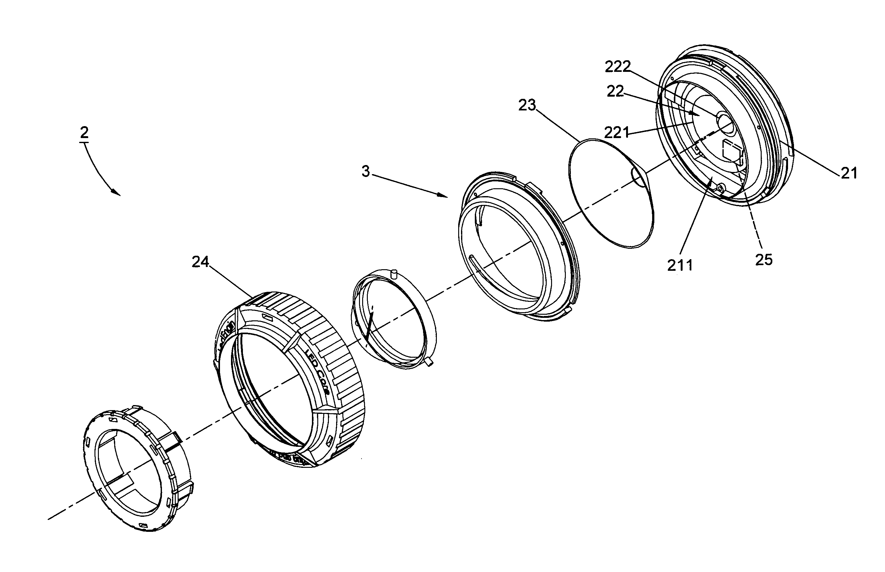
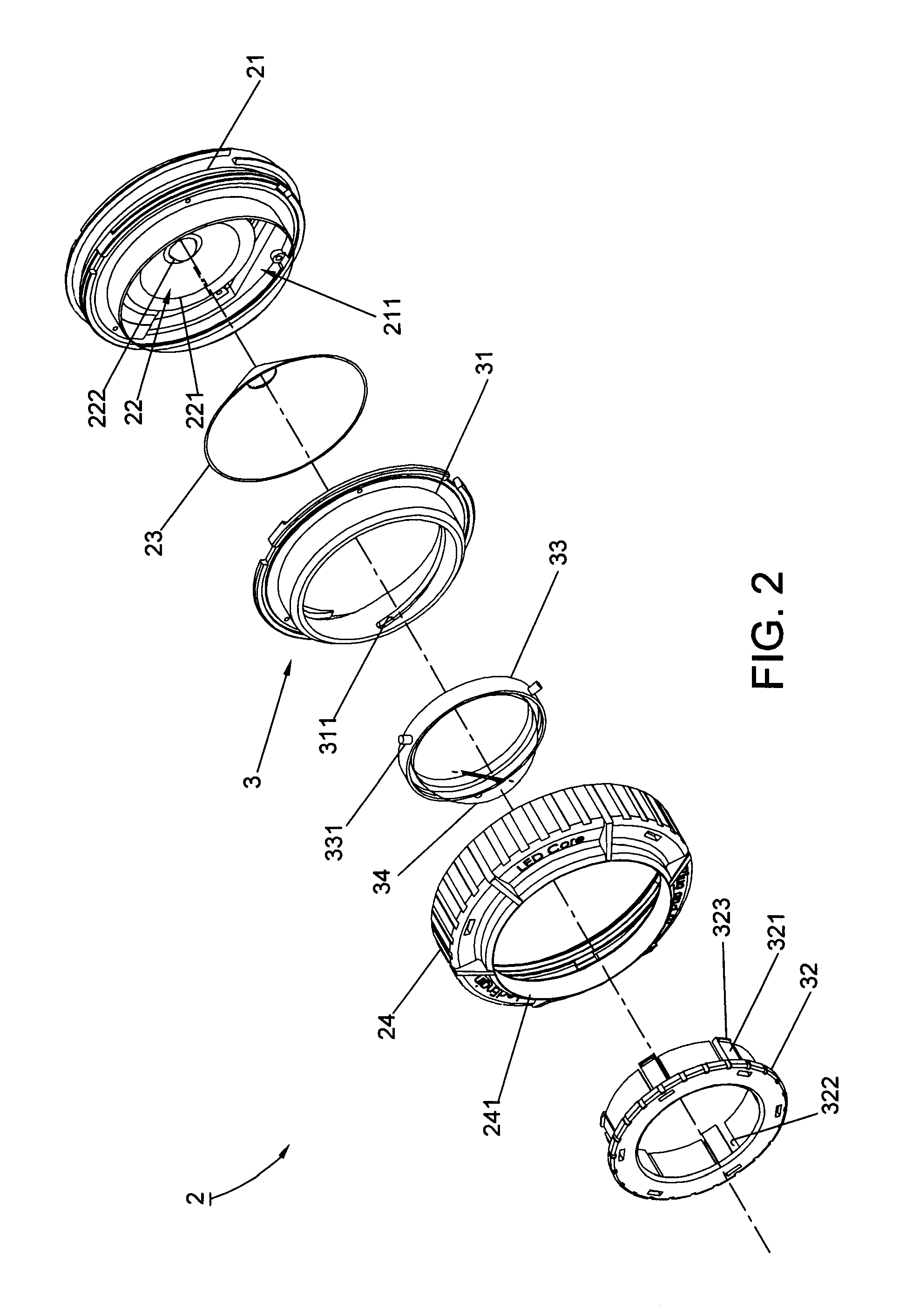
[0015]Referring to FIG. 2, a first preferred embodiment of the present invention is shown. An LED lamp holder 2 for adjusting a beam spread thereof comprises a seated body 21 with an accommodating room 211, a circuit unit 22 as well as a projecting unit 23 respectively disposed within the accommodating room 211, and a cover unit 24 connected with the seated body 21. Wherein, an adjusting module 3 is disposed between the seated body 21 and the cover unit 24. Further, the circuit unit 22 includes a holding plate 221 disposed in the accommodating room 211 and at least one LED member 222 disposed on the holding plate 221. Herein, the projecting unit 23 is mounted on the holding plate 221. An aperture 241 is further defined on the cover unit 24.

[0016]Continuingly, the adjusting module 3 has a holder 31 connecting to the seated body 21, a motivating member 32...


PUM


Abstract

An LED lamp capable of adjusting a beam spread thereof mainly comprises an adjusting module disposed between a seated body and a cover unit. The adjusting module includes a holder connecting to the seated body, a motivating member traveling within an aperture of the cover unit, an engaging member propping the motivating member against the holder, and a lens disposed on the engaging member. Thereby, rotating the motivating member triggers the engaging member to either move protrudently outward or draw back inward with respect to the cover unit. Accordingly, a beam angle of LED members disposed on a circuit unit of the lamp holder is able to be increasingly condensed or spread, thence promoting the luminaire efficiency of the present invention.

Description

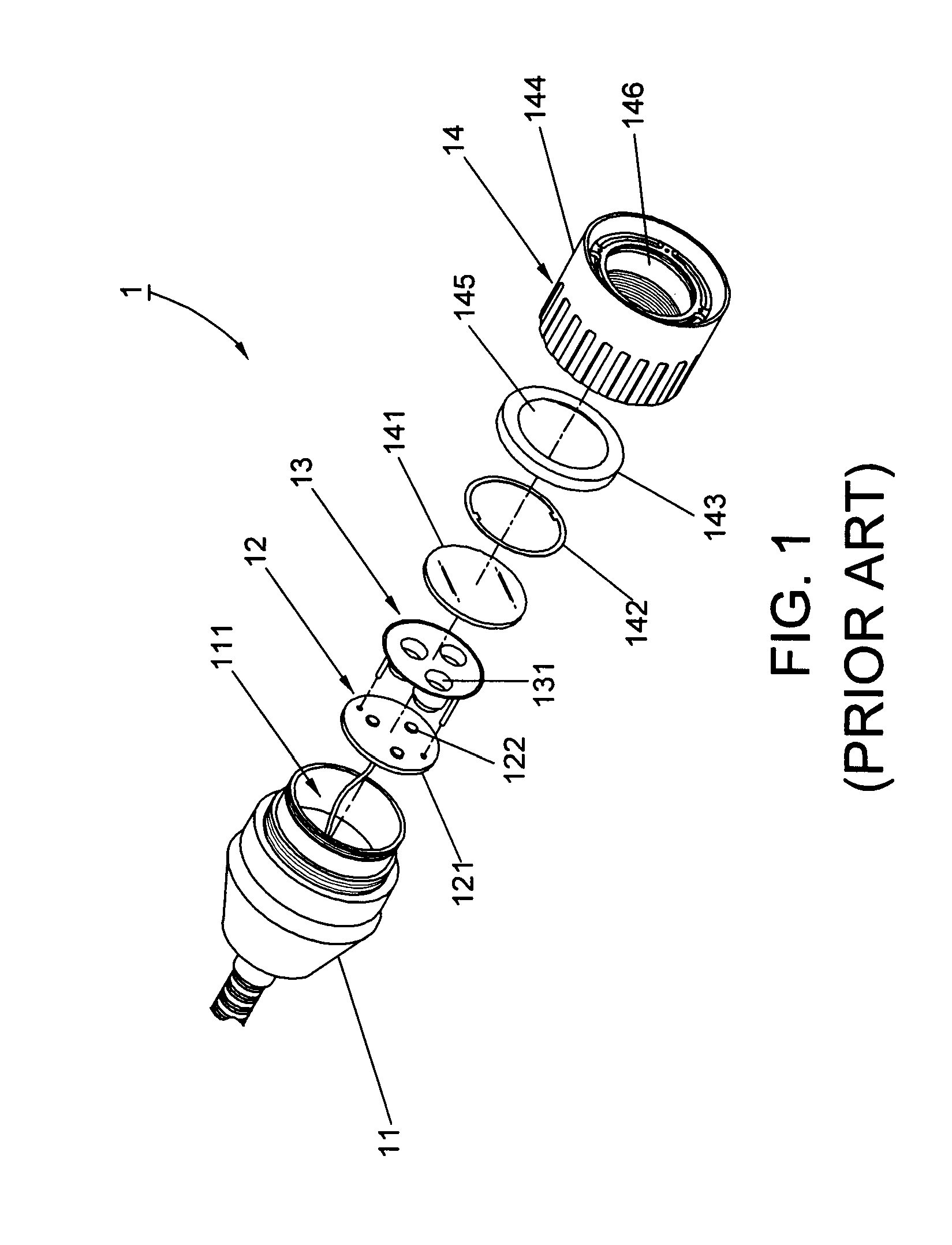
BACKGROUND OF THE INVENTION[0001]1. Field of the Invention[0002]The present invention relates to a design of an LED lamp holder, particularly to an LED lamp capable of adjusting a beam spread thereof.[0003]2. Description of the Related Art[0004]Referring to FIG. 1, a conventional LED lamp whose projecting and condensing module could be freely replaced is disclosed by a Taiwan patent No. M356844. The disclosure comprises a casing unit 11 with an accommodating room 111, a circuit unit 12 disposed within the accommodating room 111, a projecting unit 13 installed in the accommodating room 111, and a detachable cover unit 14 mounted on the casing unit 11. Wherein, the circuit unit 12 includes a holding plate 121 and at least one LED member 122 disposed on the holding plate 121. Moreover, the projecting unit 13, disposed on the holding plate 121, includes at least one projecting member 131 corresponding to the LED member 121. Further, the cover unit 14 includes a lens 141, a gasket 142, a...

Claims


Application Information

Patent Timeline
IPC IPC(8): F21S8/00
CPCF21V14/06F21Y2101/02F21V19/001F21V17/02F21Y2115/10
Inventor HUANG, TSUN-HUNGLIU, JHON-CI
Owner JIAWEI RENEWABLE ENERGY CO LTD
Learn More